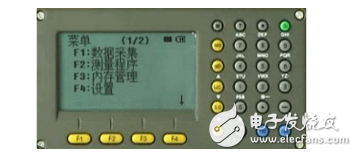
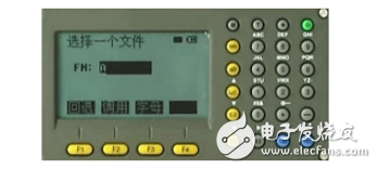
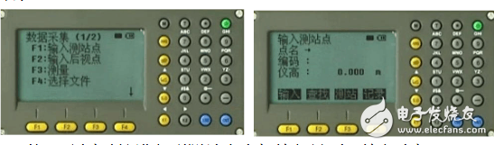
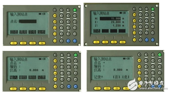
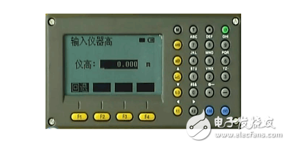
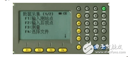
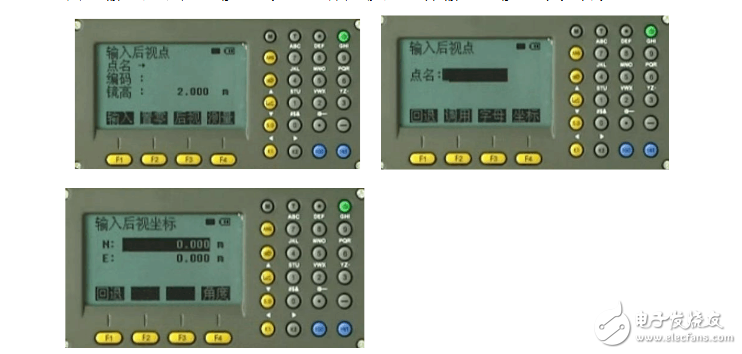
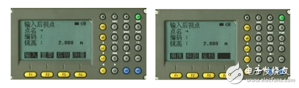
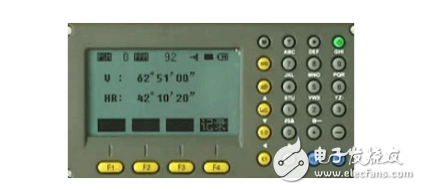
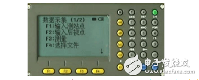
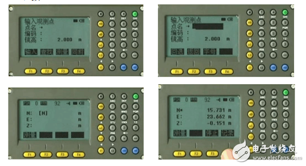
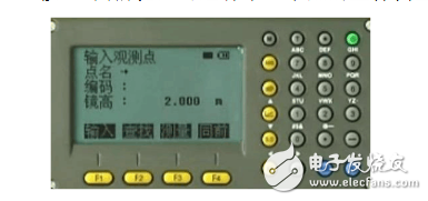
The total station, the Electronic Total StaTIon, is a high-tech measuring instrument that integrates light, machine and electricity. It is a horizontal angle, a vertical angle, and a distance (slant distance, horizontal distance). ), the height difference measurement function in one of the mapping instrument system. Compared with the optical theodolite, the electronic theodolite converts the optical dial to the photoelectric scanning dial, and replaces the artificial optical micrometer reading with automatic recording and display reading, which makes the angle measuring operation simple and avoids the reading error. Because it can complete all the measurement work on the station once it is placed, it is called the total station. It is widely used in precision engineering measurement or deformation monitoring in large-scale buildings and underground tunnel construction. The difference between a total station and an optical theodolite lies in the dial reading and display system. The horizontal and vertical dials of the optical theodolite and their reading devices are respectively angled (coded disc) or two identical grating dials and reading sensors. measured. According to the angular accuracy, it can be divided into several grades such as 0.5′′, 1′′, 2′′, 3′′, 5′′, 7′′. The total station can be used in almost all measurement areas. The electronic total station consists of a power supply part, a goniometer system, a ranging system, a data processing part, a communication interface, a display screen, a keyboard, and the like. Compared with electronic theodolites and optical theodolites, the total station has added many special components, which makes the total station more functions than other angle measuring and ranging instruments, and is more convenient to use. These special components constitute the unique characteristics of the total station. Coaxial telescope The telescope of the total station realizes the coaxial axis, the emission of the ranging light wave, and the coaxialization of the receiving optical axis. The basic principle of coaxialization is to set up a spectroscopic prism system between the telescope objective lens and the focusing lens. Through the system, the telescope is multi-functional, that is, it can aim at the target and make it image on the cross-hair reticle for angle measurement. At the same time, the external optical path system of the ranging portion enables the modulated infrared light emitted by the photodiode of the ranging portion to be reflected back through the same path after passing through the objective lens to the reflective prism, and then the return light is received by the photodiode through the splitting prism. For the distance measurement, an internal optical path system is needed inside the instrument. The modulated infrared light emitted by the photodiode is also sent to the photodiode through the optical fiber in the dichroic prism system, and the phase of the light is modulated by the inner and outer optical paths. The difference indirectly calculates the propagation time of the light and calculates the measured distance. The coaxiality allows the telescope to simultaneously measure the measurement functions of all basic measurement elements such as horizontal angle, vertical angle and slant distance. Together with the powerful and convenient data processing function of the total station, the total station is extremely convenient to use. Total station cutaway view Dual axis automatic compensation The principle of two-axis automatic compensation has been introduced in the inspection and calibration of the instrument. If the vertical axis of the total station is tilted during operation, the error of the angle observation will be caused. The observation of the left and right sides of the panel cannot be offset. The total station's unique dual-axis (or single-axis) tilting automatic compensation system monitors the tilt of the vertical axis and automatically corrects the angular error caused by the tilt of the longitudinal axis in the dial reading (some The maximum tilt of the vertical axis of the station can be allowed to ±6'). The angle error caused by the tilt of the vertical axis can also be calculated by the microprocessor automatically according to the vertical axis tilt correction calculation formula, and added to the dial reading to correct, so that the dial display reading is the correct value, the so-called vertical axis tilt Automatic compensation. The construction used for biaxial automatic compensation (existing levels, including Topcon, Trimble): using a blisters (which are not visible from the outside, not a blisters as described in the test calibration) to calibrate the absolute level, The blisters are intermediate filled liquids with gas at both ends. A light-emitting diode is placed on each of the upper sides of the blisters, and a photocell is placed on each of the lower sides of the blisters, and the light emitted by the blisters is received by a receiving light-emitting diode. Then, the intensity of the light obtained by the two diodes is compared by an arithmetic circuit. When the initial position, that is, the absolute level, the operation value is set to zero. When the whole station instrument is tilted during the operation, the arithmetic circuit calculates the difference of the light intensity in real time, and converts it into a tilted displacement, and transmits this information to the control system to determine the value of the automatic compensation. The automatic compensation method is initially calculated by the microprocessor to correct the output. Another way is to use the stepping motor to drive the micro screw to correct the offset in the direction of the axis, so that the axis is guaranteed to be absolutely horizontal. keyboard The keyboard is the hardware that the total station inputs the operation command or data during the measurement. The keyboard and display of the full-station instrument are double-sided, which is convenient for the operation of the front and back mirrors. Memory The total station memory is used to store the measured data collected in real time and then transfer it to other devices such as computers for further processing or utilization as needed. The total station memory has two types of internal memory and memory card. The total station internal memory is equivalent to the computer's memory (RAM). The memory card is an external storage medium, also known as a PC card, which acts as a computer disk. Communication Interface The total station can input the data stored in the memory into the computer through the RS-232C communication interface and communication cable, or transmit the data and information in the computer to the total station via the communication cable to realize two-way information transmission. What is total station data acquisition? Station data acquisition instructions 1. Press the MENU button to enter the main menu and press the F1 button to select the data acquisition function. 2. After selecting a file, press the Enter key (confirm) to end. 3. Press the F1 key (input to the test station), press the F1 key to enter the point name, code, and instrument height, and then press the F4 key to confirm. 4. Press F4 (coordinate key) to enter the coordinate input interface of the measurement station and input the values ​​of coordinates N, E and Z. Press the Enter key to confirm and end. Press the F4 key, record, and press the F4 key (ie: Yes, record data). 5. Then enter the input interface of the instrument, input the height of the instrument, and press the Enter key to confirm. At this point, the settings of the test site are completed. 1. Go back to the data collection menu. Press F2 in the data collection menu (enter the backsight point key) 2. Press F1 to enter the point name, code, and instrument height. Press F3 Rear View button to enter the backsight input interface. After entering the point name, press the F4 key to enter the backsight point coordinate input and press the Enter key to confirm. 2. Then press the F4 measurement button, then press the F1 angle button to display the azimuth of the backsight point and press the F4 key (ie: record). Complete the settings of the backsight point. 1. Return to the data collection menu. Press F3 (Measure) in the data acquisition menu. 2. Press F1 to enter the point name, code, and prism height of the observation point. Press Enter to confirm. Press F3 (measurement key) and press the F3 coordinate key to start coordinate measurement. After the measurement is completed, press the F4 record button to record the data. 3. Press F4 with the front button to perform the coordinate measurement of the next point. Multi Plug DC EV charger Shenzhen Hongjiali New Energy Co., Ltd. , https://www.hjlcharger.com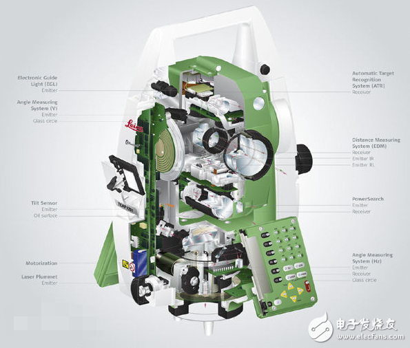
Total station