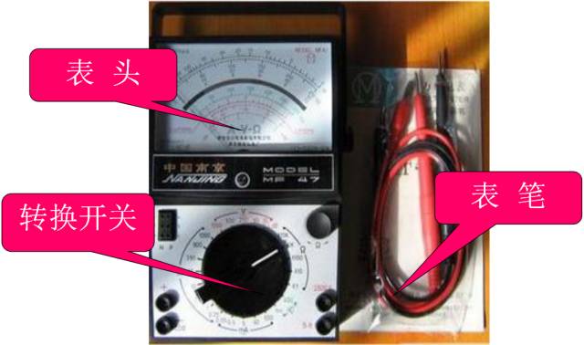
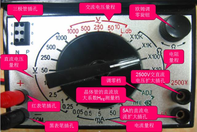
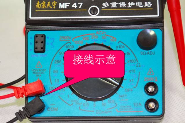
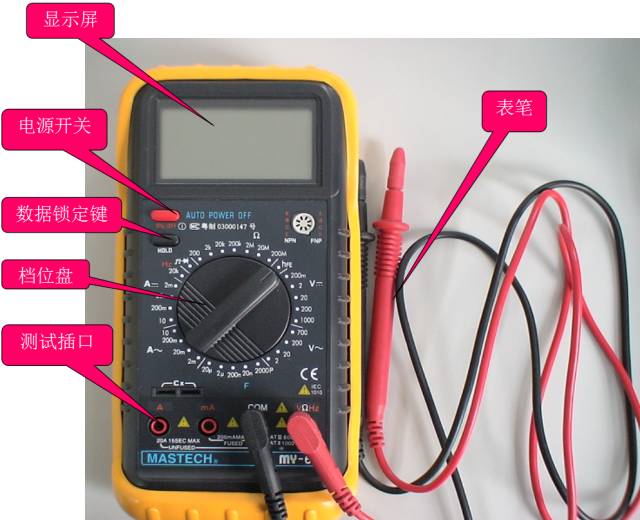
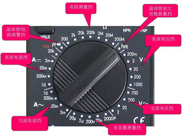
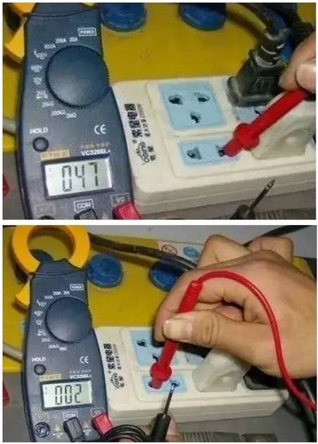
A, multimeter classification 1. There are two types of commonly used multimeters, analog and digital: The pointer type multimeter is a multi-function measuring instrument which is composed of a mechanical watch head as a core component, and the measured value is read and indicated by the head pointer; The value measured by the digital multimeter is displayed by the LCD screen directly in the form of numbers, and at the same time, some voice prompting functions are also provided. 2. Classified by shape There are desktops, pliers, handhelds, and pockets. 3. Comparison of advantages and disadvantages The reading accuracy of the analog multimeter is slightly worse than that of the digital multimeter, but the course of the hand swing is relatively intuitive and obvious, and the swing speed and amplitude sometimes can objectively reflect the size and direction of the measured value. The digital meter has high sensitivity, high accuracy, clear display, strong overload capacity, easy to carry, and easier to use. Second, the pointer multimeter There are many types of analog multimeters, but the basic structure is similar. The structure of the pointer multimeter is mainly composed of three parts: the meter head, the switch (also called the selector switch), and the measurement circuit. Header: It is a measuring display device; the head of the multimeter is actually a sensitive galvanometer Switch: Select the type and range (or magnification) of the measured electricity Measuring line: convert the measured electricity of different nature and size into direct current that the meter can accept. Table head Transfer switch Pointer multimeter use precautions when using it (1) Must be placed horizontally so as not to cause errors. (2) Do not hit hard objects or fall to the ground. (3) Do not touch the metal part of the pen with your hands. (4) When measuring a certain electric quantity, it is not possible to shift gears while measuring, especially when measuring high voltages. Otherwise, it will destroy the multimeter. If you need to shift gears, you should disconnect the test leads before changing gears. Correct wiring 1. The red meter pen is connected to the "+" polarity jack and the black meter pen to the "-" or "*" or "COM" polarity jack. 2. When measuring the DC quantity, pay attention to the positive and negative polarity so as not to reverse the pointer. 3. When measuring current, the meter should be connected in series with the circuit under test. When measuring the voltage, the meter should be connected in parallel at both ends of the circuit under test. 4. When measuring the transistor, it should be kept in mind that the red meter of the multimeter is connected to the negative pole of the battery in the watch; the black test pen is connected to the positive pole of the battery in the watch. Correct selection of measuring gear 1. The voltage switch should be placed in the corresponding voltage block when measuring the voltage, and the corresponding current block should be placed when measuring the current. 2. When selecting the current or voltage range, it is best to place the pointer over two thirds of the scale. When selecting the resistance range, it is best to place the pointer in the middle of the scale. 3. When measuring, when the measured value range is uncertain, the changeover switch should first be turned to the corresponding maximum range, and then gradually reduced to the proper range according to the degree of deflection of the pointer. After use (1) After using the multimeter, if there is no gap, set the range switch to the highest AC voltage level; if there is a neutral ("*" or "OFF"), dial it to this level. (2) When the multimeter is not used for a long time, the battery inside the watch should be taken out to prevent the leakage of the battery electrolyte and corrode the internal circuit. Third, digital multimeter Gear plate jack Digital Multimeter Precautions a If it is impossible to estimate the magnitude of the measured voltage or current in advance, you should first dial the highest range and measure once, and then gradually reduce the range to the appropriate position. After the measurement is completed, set the range switch to the highest voltage level and turn off the power. b At full scale, the meter will only display the digit "1" in the highest position. All other digits will disappear. In this case, a higher range should be selected. c When measuring the voltage, connect the digital multimeter in parallel with the circuit under test. When measuring the current, it should be connected in series with the circuit under test. When measuring the amount of DC, it is not necessary to consider the positive and negative polarity. d When the AC voltage is blocked to measure the DC voltage, or if the DC voltage is not used to measure the AC voltage, the display will show “000â€, or the digits on the lower digit will appear to jump. e It is prohibited to change the range when measuring high voltage (above 220V) or high current (above 0.5A) in order to prevent arcing and burn the switch contacts. When the display when f "", "BATT" or "LOW BAT", it indicates that the battery voltage is below the operating voltage. Four, multimeter use experience 1. Multimeter measuring leakage method: With the multimeter's on-off, the amount of ground and measured circuit parts, if the table shows a resistance, it is judged not to be insulated. But in fact if you measure leakage, you should use a megohmmeter, that is, shake the meter. Because the voltage of both ends of the pen is very low when measured by a multimeter, it usually does not exceed 9V, and it cannot break through the gap leakage. The megohmmeter can reach more than 1000v. Insert the multimeter connector into the corresponding terminal of the measuring alternating current, then use a pen to measure the zero line or the ground line, another pen to measure the place where you suspect leakage, and see the universal number. If it is 0, then say there is no leakage, No voltage! If it is 220 or other than 36V voltage display number, it is leakage, indicating that it is not safe! Measure the insulation resistance with the multimeter resistance file 200M to determine which line is leaking or which two lines are shorted. Methods as below: Measure the insulation resistance of the live wire and the neutral wire, measure the insulation resistance of the live wire and the ground wire, and measure the insulation resistance of the neutral wire to the ground wire. If the short-circuit insulation resistance is substantially zero. Know which line is leaking and use the segment search method to gradually narrow down the fault. Or use the exclusion method to separate the lines after a period of power-on test. 2. How to distinguish the zero line and FireWire multimeter: In general, to identify the neutral line in the city power, FireWire, non-use of low-voltage test pencil is not, with a multimeter can also distinguish the FireWire and the neutral line it? The answer is yes, as follows: Switch the multimeter's range switch to the AC voltage 250V or 500V. The black meter pen is connected to the indoor water pipeman wet ground, land, etc. The red meter pen is in contact with the power cord or power socket hole, and the voltage value indicated by the multimeter is high, A zero line with a low or zero voltage. 3. Use a digital multimeter to measure the zero fire: With a multimeter, you can easily measure your home's zero line FireWire, as long as you use a digital multimeter, clamp-type multimeter, pointer mechanical multimeter AC voltage file can be. Multimeter range switch to the AC voltage range (it should be so multimeter has this function, ranging from 200mV to 750V, generally choose 200V file, some clamp meter without 200V file can choose a larger range. Pointer multimeter gear can be selected to 10V 100V) and then red and black pens are inserted in the V / COM (usually measuring 220V home appliance voltage jack) black winding around the left hand 2-3 laps (see Figure Of course, the more the better, pay attention to: At this time, the black pen metal needle must not touch the hand, to prevent electric shock and then you can test it, right received red table pen respectively measure the socket or zero fire line, you note the two measurements As a result, there must be a large and small voltage between them. The large measured voltage is the hot line, and the small voltage is certainly the zero line. If the geodesic line is definitely no smaller voltage or even no voltage (see your home The ground wire is not connected!) The difference between the measured values ​​of the voltages of the neutral wire and the live wire is clear at a glance. Five, multimeter measurement techniques 1, measuring the horn, headphones, dynamic microphone: Use R × 1Ω file, any table pen to one end, the other table pen to touch the other end, when normal will issue a crisp volume "click" sound. If it does not ring, then the coil is broken. If the sound is small and sharp, there is a rubbing problem and it cannot be used. 2 Estimating the size of the skin-level capacitor: Use R×10kΩ, but only measure the capacitance above 1000pF. For a capacitance of 1000pF or slightly larger, as long as the hands are slightly swung, the capacity is considered enough. 3 If the capacitance is measured for leakage: For a capacitor over a thousand microfarads, it can be quickly charged with an R×10Ω file, and the capacitance of the capacitor is estimated initially. Then, the capacitance is changed to R×1kΩ for a while. At this time, the pointer should not be measured. Return, but should stop at or very close to ∞, otherwise there is leakage. For some of the dozens of micro-methods of timing or oscillating capacitors (such as the resonant capacitor of a switching power supply for color TVs), their leakage characteristics are very high, so long as there is a slight leakage, they cannot be used. At this time, they can be charged after R×1kΩ. Then continue to use R × 10kΩ file to continue measuring, the same hands should stop at ∞ and should not return. The method is: First put a table in R × 10k file, the black and red pens are connected to the cathode and the anode of the voltage regulator respectively. At this time, the actual working status of the voltage regulator is simulated, and another table is placed. The voltage file V×10V or V×50V (according to the voltage regulation value), the red and black table pens are respectively connected to the black and red table pens of the table. At this time, the measured voltage value is basically this Regulator voltage regulator value. Said “basically†because the bias current of the first regulator is slightly smaller than the bias current when the regulator is normally used, so the measured regulation value will be slightly larger, but it is basically the same. . This method can only estimate the voltage regulator whose voltage regulation value is less than the high voltage battery voltage of the pointer meter. If the regulator's voltage regulation value is too high, it can only be measured with an external power supply. (In this case, we choose the high voltage battery voltage to be 15V which is more suitable than 9V when using the pointer meter.) The first method: For a pointer table with a triode hFE jack, after the b-pole is measured, insert the triode into the jack (optional b-pole can be inserted accurately), measure the hFE value, and then The tube was inverted and measured again, and the hFE value was measured once. The position of each pin insertion was correct. The second method: For the table without the hFE measuring socket, or the tube is too inconvenient to insert the jack, you can use this method: For the NPN tube, first measure the b pole (the tube is NPN or PNP and its b foot It is very easy to measure, right?), the table is placed in R × 1kΩ file, the red table pen to the e-pole of the hypothesis (note that the red table pen's hand does not touch the table pen tip or the pin), the black table pen to accept the hypothesis c pole, at the same time with your fingers pinching the table pen tip and this pin, the tube to pick up, use your tongue tip b pole, see the head pointer should have a certain deflection, if you are correctly connected to the table pen, pointer deflection will Larger, if you do not get it right, the deflection of the pointer will be smaller and the difference is obvious. From this, the c and e poles of the tube can be determined. For the PNP tube, the black pen should be connected to the hypothetical e-pole (hand not touching the pen tip or the pin), the red pen should be connected to the assumed c-pole, and the tip of the pen should be held between the finger and the pin, and then the tongue should be clicked. Extremely, if the pens are correctly connected, the head pointer will be deflected relatively large. Of course, the measurement pen must be exchanged for two measurements, and the final decision can be made after comparing the readings. This method is applicable to all shape triodes, convenient and practical. Based on the deflection of the hands, the ability to amplify the tube can also be estimated, which of course is based on experience. The third method: first determine the NPN or PNP type of the tube and its b-pole, the table is placed in R × 10kΩ file, the NPN tube, the black table pen to the e-pole, when the red table pen then c-pole, the hands may have a certain Deflection, for the PNP tube, the black pen is connected to the c-pole, and when the red pen is connected to the e-pole, the hands may have a certain deflection, and in turn there will be no deflection. From this, it is also possible to determine the c and e poles of the triode. However, for high pressure pipes, this method is not applicable. For the common imported model of high-power plastic tube, the c is basically in the middle (I haven't seen b in the middle). The b power of the medium and small power tubes may be in the middle. For example, commonly used 9014 triode and its series of other types of transistors, 2SC1815, 2N5401, 2N5551 and other triodes, the b very much in the middle. Of course, they also have c in the middle. Therefore, when repairing and replacing the triodes, especially those small power triodes, they can't be used directly and they must be directly installed. It must be tested first. SUNLUX IOT Technology (Guangdong) INC. , http://www.sunluxbarcodereader.com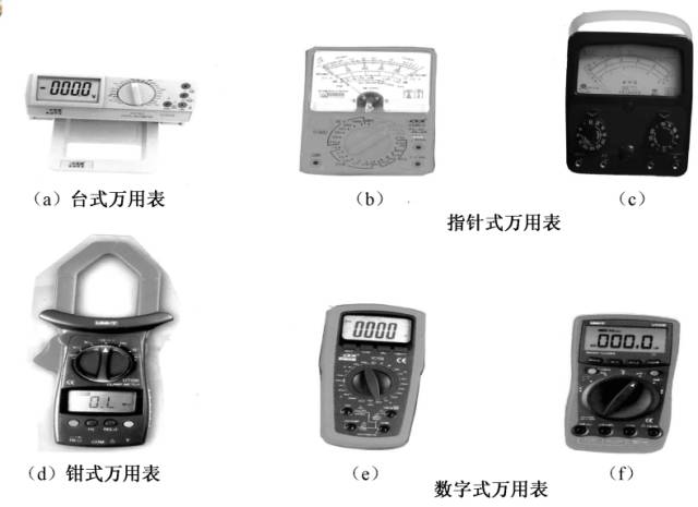


2, measuring capacitance:
With the resistance file, select the appropriate range based on the capacitance of the capacitor, and note that the capacitor should be connected to the positive electrode of the black pen of the electrolytic capacitor when measuring. 1 Estimating the capacity of the microwave method capacitor: It can be judged based on the maximum amplitude of the pointer's swing by experience or reference to the standard capacitor of the same capacity. The referenced capacitors do not need to have the same voltage value, so long as they have the same capacity. For example, a 100μF/250V capacitor can be used to refer to a 100μF/25V capacitor. As long as their pointers oscillate at their maximum amplitude, the same capacity can be determined.
3, in the road test diode, transistor, regulator tube is good or bad:
Because in the actual circuit, the bias resistance of the triode or the peripheral resistance of the diode and the zener is generally relatively large, most of which is more than a few hundred kilo-ohms. In this way, we can use R×10Ω or R×1Ω of the multimeter. Come on the road to measure the quality of the PN junction. When measuring on the road, use PN 10Ω to measure the PN junction should have more obvious positive and negative characteristics (if the difference between the positive and negative resistance is not obvious, you can use R × 1Ω file to measure), the general forward resistance in R When the ×10Ω profile is detected, the hands should indicate about 200Ω, and when the R×1Ω profiles are measured, the hands should indicate about 30Ω (a slight deviation may occur depending on the phenotype). If the measured value of the positive resistance is too large or the value of the reverse resistance is too small, this indicates that there is a problem with this PN junction. This tube is also problematic. This method is particularly effective for maintenance, it can find out bad tubes very quickly, and can even measure tubes that have not completely broken but have bad characteristics. For example, when you measure the positive resistance of a PN junction with a small resistance value, if you solder it off and test it with a common R×1kΩ file, it may still be normal. In fact, the characteristics of the tube have deteriorated. Not working or unstable.
4, measuring resistance:
It is important to select a range. When the pointer indicates 1/3 to 2/3 full scale, the measurement accuracy is the highest and the reading is the most accurate. It should be noted that, when using a large resistance value resistor of Megaohm in the R×10k resistor range, do not pinch the finger across the resistor so that the human resistance will make the measurement result too small.
5, test voltage regulator diode:
The voltage regulator value that we usually use is generally greater than 1.5V, and the resistance table below R×1k of the pointer table is powered by the 1.5V battery in the watch, so, use the resistance file below R×1k Measuring a Zener tube is like a diode and has complete unidirectional conductivity. However, the R×10k file of the pointer table is powered by a 9V or 15V battery. When a voltage regulator with a voltage regulation value of less than 9V or 15V is tested with R×10k, the reverse resistance value is not ∞, but there is a certain value. Resistance, but this resistance is still much higher than the forward resistance of the regulator. In this way, we can initially estimate the quality of the regulator. However, a good regulator must have an accurate regulator. How do you estimate this regulator under the amateur condition? It is not difficult to find a pointer table.
6, measuring triode:
Usually we need to use R×1kΩ file, whether it is NPN tube or PNP tube, whether it is a low-power, medium-power, high-power tube, test its be-junction cb junction should show the same unidirectional conductivity with the diode, reverse Resistance is infinite, its forward resistance is about 10K. In order to further evaluate the quality of the pipe, if necessary, it is also necessary to change the resistance range to make multiple measurements. The method is: set R × 10Ω to measure the forward conduction resistance of the PN junction is about 200Ω; set R × 1Ω profile PN junction forward conduction resistance is about 30Ω or so, (the above is the 47 type of table measured data, other models of the table is roughly different, you can test a few good tube summary, to be aware) if the reading is too large Too much, it can be concluded that the characteristics of the tube are not good. Can also be placed in the table R × 10kΩ re-measurement, low pressure tube (basically, the pressure of the triode is more than 30V), the cb junction reverse resistance should also be in ∞, but the reverse resistance of the be junction There may be some, the hands will be slightly deflected (usually will not exceed 1/3 of the full scale, depending on the pressure resistance of the tube). Similarly, when measuring resistance between ec (for NPN tube) or ce (for PNP tube) with R×10 kΩ, the hands may be slightly deflected, but this does not mean that the tube is bad. However, when measuring the resistance between ce and ec in the following range of R×1kΩ, the meter indication should be infinite, otherwise the tube is a problem. It should be noted that the above measurements are for silicon tubes and not for manifolds. However, it is rare to see it now. In addition, said "reverse" is actually different for the direction of the NPN tube and the PNP tube for the PN junction.
Now that most of the common transistors are plastic, how can we accurately determine the three pins of a triode which are b, c, and e?
The b-pole of the transistor is very easy to measure, but how to determine which is c or e? Here are three recommended methods: