About SPI Transport Procedure stm32 SPI Configuration
SPI (Serial Peripheral interface), as its name suggests, is a serial peripheral interface. SPI is a high-speed, full-duplex, and synchronous communication bus. It only uses four wires on the pins of the chip, which saves the pins of the chip and saves space and convenience for the layout of the PCB. The main application is SPI. In the EEPROM, FLASH, real-time clock, AD converter, and digital signal processor and digital signal decoder.
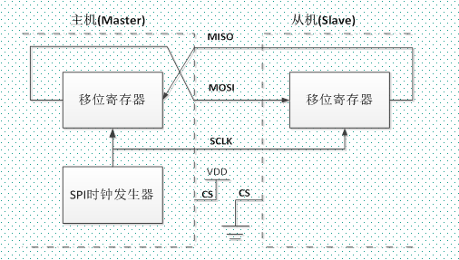
Simple internal structure diagram of SPI
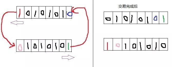
About the SPI transmission process (following drawing by the soul artist)
The SPI contains four lines:
1. SS (Slave Select): Chip select signal line. When there are multiple SPI devices connected to the MCU, this chip select signal line of each device is connected to the MCU's separate pin, while other SCK, MOSI, MISO Lines are multiple devices connected in parallel to the same SPI bus. When the SS signal line is low, the chip select is valid and SPI communication is started.
2. SCK (Serial Clock): A clock signal line generated by the main communication device. Different devices support different clock frequencies.
3. MOSI (Master Output, Slave Input): Master Output, Slave Input Pins
4. MISO (Master Input, Slave Output): Master Input, Slave Output Pins
About SPI mode
Four modes can be divided according to the difference of SPI clock polarity (CPOL) and clock phase (CPHA) configuration
The clock polarity refers to when the SPI communication device is in the idle state (or when the SPI communication starts, ie when the SS is low level). When the SCK level signal CPOL=0, the SCK idle state is the low level, and when the CPOL=1 is in contrast.
The clock phase refers to the data sampling time. When CPHA=0, the MOSI or MISO data line starts sampling on the first edge of the clock line (odd edge).
When CPHA = 1, the MOSI or MISO data line starts sampling on the second edge of the clock line (even edge)
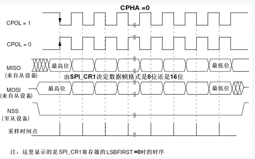
Step analysis: SS chip select signal line is pulled low --> data sampling according to CPOL and CPHA
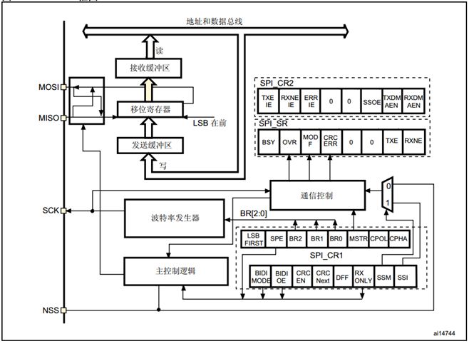
Stm32 SPI interface block diagram
Stm32 SPI configuration process
1, configure the related pin multiplexing function to enable the SPIx clock
Void GPIO_Init(GPIO_TypeDef* GPIOx, GPIO_InitTypeDef* GPIO_InitStruct);
2, initialize the SPIx, set the SPIx mode of operation
Void SPI_Init(SPI_TypeDef* SPIx, SPI_InitTypeDef* SPI_InitStruct);
3, enable SPIx
Void SPI_Cmd(SPI_TypeDef* SPIx, FunctionalState NewState);
4, SPI transmission data
Void SPI_I2S_SendData(SPI_TypeDef* SPIx, uint16_t Data);
Uint16_t SPI_I2S_ReceiveData(SPI_TypeDef* SPIx);
5, check the SPI transmission status
FlagStatus SPI_I2S_GetFlagStatus(SPI_TypeDef* SPIx, uint16_t SPI_I2S_FLAG);
Dance Floor Led Display,Dance Floor Led Screen,Led Screen Dance Floor,Led Dance Floor For Sale
ShenZhen Megagem Tech Co.,Ltd , https://www.megleddisplay.com