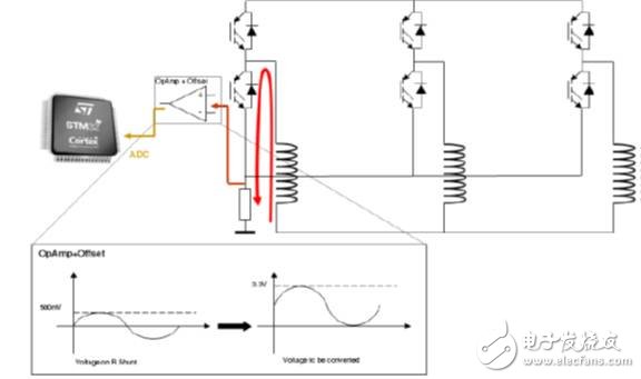
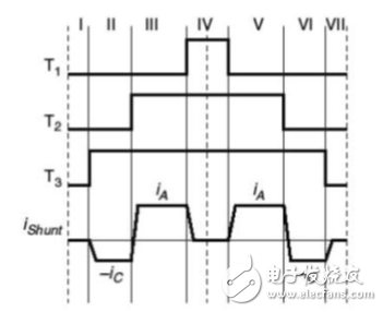
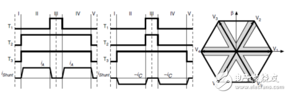
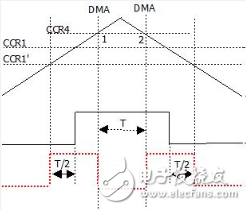
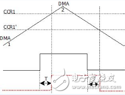
Foreword The motor control single-resistance sampling mechanism collects two-phase current ADC data in one PWM waveform, but only one current ADC data can be obtained under certain sector boundary conditions. The PWM waveform needs to be deformed to construct the current sampling region. Background introduction According to the motor control topology, single-resistance sampling can obtain two-phase current data in one PWM control cycle: A two-phase current signal cannot be obtained at the edge of the sector. Waveform generation The ST patent method is to generate a deformed waveform in the middle part of the waveform, and two-phase current ADC data can be obtained on the deformed waveform ; Of course, there are currently more popular waveform shifting methods that can achieve the same effect. The waveform is as follows: The STM32 series MCU Timer has enough functions to generate the above two waveforms. The mechanism is as follows: PWM wave intermediate deformation 1. Set the DMA channel of CCR4, and set the preload of Timer1 to be disabled at this time; TIM_OC1PreloadConfig(TIM1, TIM_OCPreload_Disable); 2. Generate a DMA event in the CCR4 comparison value section; DMA_InitStructure.DMA_PeripheralBaseAddr= (uint32_t)(&(TIM1->CCR1)); DMA_InitStructure.DMA_MemoryBaseAddr= (uint32_t)(uint32_t)(hDmaBuff2); DMA_InitStructure.DMA_DIR = DMA_DIR_PeripheralDST; DMA_InitStructure.DMA_BufferSize= 2u; .... TIM_DMACmd (TIM1, TIM_DMA_CC4, ENABLE); 3. Modify the CCR1 data directly to the periodic data +1 at 1 o'clock; 4. Modify the CCR1 data to the data of CCR1' at 2 o'clock; 5. The time calculation is set according to the above illustration, and the middle recess time is the sum of the complementary waveform times on both sides. Waveform shift deformation 1. Set the DMA channel of the update event of Timer1 DMA_InitStructure.DMA_PeripheralBaseAddr =(uint32_t)(&(TIM1->CCR1)); DMA_InitStructure.DMA_MemoryBaseAddr =(uint32_t)(uint32_t)(hDmaBuff2); DMA_InitStructure.DMA_DIR = DMA_DIR_PeripheralDST; DMA_InitStructure.DMA_BufferSize = 2u; ...... TIM_DMACmd (TIM1, TIM_DMA_Update, ENABLE); 2. Update the CCR1 data to CCR1 data at 1 o'clock; 3. Update the CCR1 data to CCR1' data at 2 o'clock; 4. Ensure that the shift time is the same before and after. Shenzhen Jinziming Electronic Technology Co.,LTD , https://www.powerchargerusb.com