Most embedded systems provide only a few buttons and fewer pixels, while the processor has limited computing power (such as 8/16-bit microcontrollers), it is not suitable to run commercial GUI graphics library (such as uC/GUI, miniGUI, QT Etc) but still have to provide GUI functionality for the user. A representative hardware platform is as follows, providing six input keys: move up, move down, move left, move right, determine and cancel; there is an LCD, which does not limit the physical size and the number of pixels. This article describes a simple GUI design principle based on the above hardware platform, which provides a window system and therefore has a better display effect. The general LCD display module includes three parts: a controller, a driver, and a liquid crystal display, and external pins are provided for connection of the embedded processor. Take TRULY company's LCD display module MST-G320240DBSW-75W-E as examples, its controller is RA8835, the pin definition of the module is shown in Table 1 below. [1] Table 1 Examples of LCD pins The hardware design requires that the LCD module pins be properly connected to the processor control pins. For most microcontrollers, it is a good choice to connect the LCD module pins to common I/O ports. Figure 1 shows the schematic of the AT89S52 microprocessor connected to a 20-pin LCD module. Figure 1 MCU I/O Connection LCD Module Another advanced wiring method is to connect it to the Asynchronous Memory interface (if the processor is equipped), so that the operation of the LCD is just like accessing ordinary memory (such as FLASH), which provides great convenience, as shown in FIG. 2 . Figure 2 ASYNC MEMORY connection LCD module The LCD controller is the core of the LCD module. Driving an LCD module is essentially the process of writing a series of instructions to the LCD controller. [2] Figure 3 bus timing Figure 3 shows the bus timing of the LCD controller RA8835. For the way that ordinary I/O ports are connected to the LCD, the driver needs to generate high and low levels in sequence for the corresponding pins, as shown in the following code: (The statement that defines the macro for the pin is omitted.) Void lcd_cmdwrite(unsigned char cmd) { LCD_CS = 0; /* Enable access LCD */ LCD_CD = 1; /* 0=Data; 1=Command */ LCD_WR = 0; /* Enable write */ LCD_RD = 1; /* Insure read signal is invalid */ LCM_DATA = cmd; /* Put command value into port */ LCD_WR = 1; /* Disable Write */ LCD_CS = 1; /* Disable access LCD */ } If the Asynchronous Memory interface of the embedded processor is connected to the LCD bus, the delay time of the interface needs to be set in order to comply with the bus timing of the LCD in Fig. 3, and then the driver will be simplified to write the peripheral memory. For the wiring in Figure 2, the driver code for writing the LCD command register is as follows: #define LCD_START_ADDR 0x20100000 /* BANK1 */ #define LCD_DATA_ADDR (LCD_START_ADDR) /* Data */ #define LCD_REG_ADDR (LCD_START_ADDR+2) /* CMD */ #define p_wLcdDataAddr ((REG16*)LCD_DATA_ADDR) #define p_wLcdRegAddr ((REG16*)LCD_REG_ADDR) #define WR_LCD_REG(wRegVal) *p_wLcdRegAddr = wRegVal; LCD controller instructions are generally organized into register formats: register name + value. Still referring to the above example, the command to set the cursor address for controller RA8835 is: register name (CSRW) 0x46, value is 2 bytes (cursor position). The register name is written into the instruction input buffer (ie, A0 = 1), and the value is written into the data input buffer (ie, A0 = 0). The basis for drawing any graphic or file on an LCD is to draw pixels, so the first thing that needs to be done is to manipulate the pixels. The interface for operating one pixel is X coordinate, Y coordinate, and action (lighting or erasing). The algorithm is as follows: 1. According to the X and Y coordinates combined into LCD cursor values ​​and write LCD controller; 2. Read current RAM value under cursor from LCD controller; 3. According to the action (light or erase) to modify the RAM value corresponding pixel BIT value; 4. Write the cursor value to the LCD controller again (read RAM causes the cursor to move); 5. Write the modified value to the LCD controller's RAM area. Once you've finished pixel manipulation, you can apply advanced drawing actions: text, images, geometry, and more. Figure 4 shows the software layer of this GUI design. The introduction of layering brings many benefits: [3] Reduce the complexity of each layer only focus on their own needs to achieve the realization of high cohesion; Improve portability No matter you replace the processor or the LCD only need to modify the bottom part; Improve performance Using efficient algorithms to optimize performance only needs to be modified. Figure 4 GUI software hierarchy For a lightweight embedded GUI, the window is a very important graphic carrier. Generally, an embedded GUI only contains one window. The currently displayed window is an active window, and the rest are all sleep windows. So the window has 2 states: Active period: processing messages, responding to actions such as acquiring real-time data and refreshing the screen; Sleep period: no response to external messages, release of resources, such as hardware and software entities; The window system is logically divided into two layers: the window server and the client, as shown in Figure 5. External messages (user keys, data updates, etc.) are first passed to the window server. The server then sends the message to the current active window. The active window performs corresponding processing according to the message type. In addition, the active window can also send a request to the server, such as switching windows. Wait. Figure 5 Window Server and Client In the GUI design, messages are an important mechanism for communication of various objects. There are various kinds of communication between windows. If messages are encoded? Figure 6 shows a reference. The message is essentially a 32-bit integer. In fact, many RTOS messaging is also of this type. Take the lower 8 bits for the event code and the higher 24 bits for the type code. [4] A maximum of 256 events of any type is supported, and only one bit can be typed. Otherwise, event determination errors will be caused. When the encoding is correct, the type must be an integral power of 2, so an algorithm that checks the power of the whole power can be used to detect the correctness of the message. Let uMsg be the message value, then there are: uTemp = uMsg & 0xFFFFFF00UL; /* fetch type encoding value */ If (0 == (uTemp & (uTemp - 1))) is encoded correctly Else encoding error Figure 6 message encoding Designing the window with an object-oriented approach As shown in Figure 7, each window has its own ID, and the ID value of its surrounding neighbor window is used for window switching; the private data space is used for window's personalization. The window object contains 3 methods: Init() is used to draw the window and initialize the window resource; ProcMsg() handles all messages passed to this window; Close() closes the window and frees resources at the same time. Figure 7 window object design The pointers of multiple windows are organized into an array to form the window object group shown in FIG. 8, which facilitates the addressing of the windows. Figure 8 window object group Figure 9 shows the relationship between the window and the neighbor window, if the current active window is 11, in response to the user button up / down / left / right to switch the window, you can directly take the ID of the corresponding neighbor window, this operation is very convenient Sex. Figure 9 window and neighbor window addressing The status bar is generally at the bottom of the window, and its typical structure is shown in Figure 10. It generally provides the following methods: Init(): Initialize the status bar object; Visible (): Display the status bar object, respond to external messages in real time; Invisible(): no longer displays the status bar object, ignoring external messages; ChangeLinkStat(): Update online/offline status; UpdateDate(): Update the current date UpdateTIme(): Update the current time The private display space is provided to the window for personalization. Its principle is: no matter which window is used, it is “who assigns, who recyclesâ€, that is, when the window is closed, all display contents in the private display space need to be cleared. The lightweight embedded GUI designed in this paper has been used stably for many years in an industrial control product. The product uses TRULY's 320x240 pixel LCD. Using layered and object-oriented design, the software system is easy to transplant and develop; the simplistic design makes the system exceptionally stable; in addition, it occupies few resources, which is unmatched by the commercial GUI. On this basis, you can also extend the functions of more advanced graphic controls. See the companion article "Lightweight Embedded GUI Advanced Function Implementation." Back-Up Ups,Avr Boost And Buck,Battery Low Voltage Protection,Dual Voltage Power Supply Shenzhen Unitronic Power System Co., Ltd , https://www.unitronicpower.com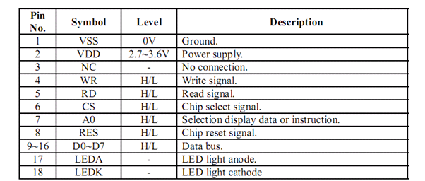
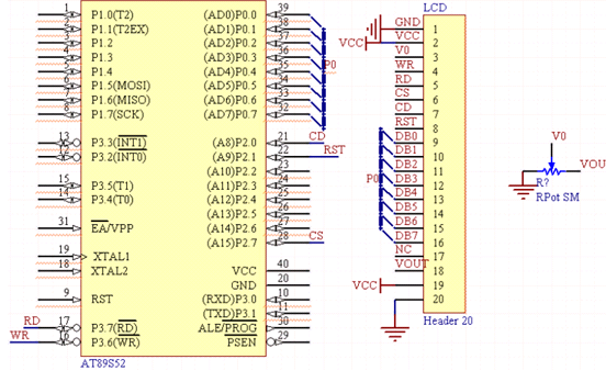
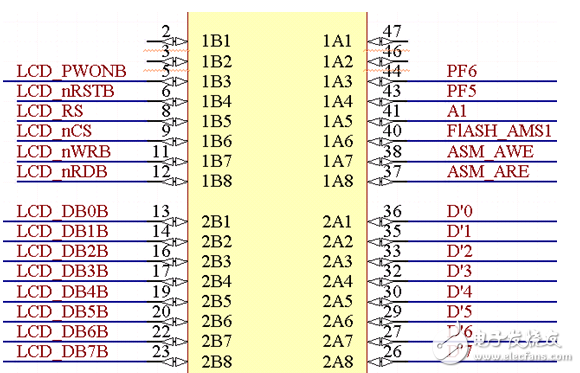
1 Introduction