Discuss the effect of capacitance on the stability of the op amp
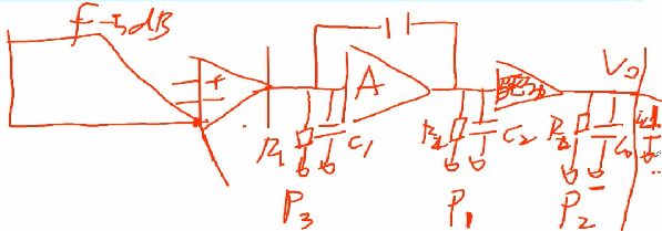
Today we have come to learn about the effect of capacitors on the stability of op amps. This is the last part. After two summing up and reviewing sessions, the entire content of the op amps enhancement class is over. I feel there is still something to be done. Let's first look at the effect of the output capacitor on stability. As mentioned in the previous lesson, when the op amp is connected in the form of a follower, the corresponding phase margin will be smaller and the stability will be poorer. Adding a 100pF or 50pF capacitor to the end will degrade the stability of the op amp. Since the op amp is internally composed of three stages, the input stage, the amplifier stage, and the driver stage, the output of each stage will pass through the resistor and capacitor. The parallel connection, according to the content of the 20th set, we know that the parallel connection of resistors and capacitors will produce a pole, so the resistance and capacitance of the input stage, amplifier stage and driver stage will introduce a pole, in which the pole of the amplifier stage is the low frequency pole. The pole of the input stage is the high-frequency pole, and the pole of the drive stage is between the two. When a capacitor is connected to the output of the op amp, the pole frequency of the drive stage will be reduced, so that the phase angle will reach -180 degrees in advance, making the phase The angular margin becomes smaller, thereby deteriorating the stability.
The corresponding solution has two kinds. One is to solve the problem by connecting a resistor in parallel with the output capacitor. The shunt resistor increases the pole frequency of the driver stage. However, there is a problem. The shunt resistor will become a part of the load current. Another method, as shown in the figure below, the output is connected to the capacitor ground through the resistor. This will also cause problems. Current will flow through the resistor and the resistor will share a part of the voltage so that the output of the op amp and the capacitor voltage are different. The resistance of the resistor is very small.
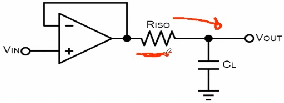
As to why the series resistance solves this problem, it will return to what we have learned before. Although it does not change the pole, it introduces a zero, which cancels out the role of the pole, making the phase not reach -180 Before returning to -90 degrees.

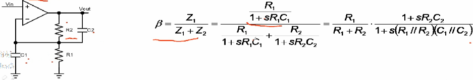
Next, look at the effect of the input stage capacitance on the stability of the op amp. The following figure shows the non-inverting amplifier and is capacitively grounded at the inverting input.
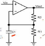
After analyzing the feedback link, we got the feedback link as a first-order system. As mentioned before, the operational amplifier can be equivalent to an ideal first-order system, so that the entire system is a second-order system, and the stability of the second-order system deteriorates. Because of the introduction of capacitance, the stability of the system will be degraded. When R2 is large, the frequency of this pole will be relatively low. This will have a greater impact on stability. When it is sometimes necessary to connect the circuit to the form of a follower, It is common to solder only R2 on the PCB but not R1 so that as long as R2 is large enough, a large C1 will not produce a pole with a low frequency, and sometimes there may not be a capacitor on the board. Just because one end of R2 is far away from the inverting input, the parasitic capacitance exists between the copper traces and the copper on the plane. The combination of this capacitor and the large R2 will also bring bad stability to the loop. The effect of the improvement is that the first kind can be reduced by the feedback resistance so that the frequency of the pole is not too low.
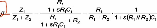
The second is to make the feedback loop not a first-order system by using a reasonable shunt capacitance at the R2 terminal, which cancels out the influence of the input capacitance.
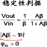
Reviewing the stability criterion of the previous set, the phase margin is the phase at which the loop gain is 1 plus 180 degrees. Of course, the larger the 1/B, the better the loop stability, and of course the worst case is Follow the form of followers. In order to be able to be equivalent to an ideal first-order system, the op amp is internally compensated by a capacitor, so that the main pole frequency is relatively low, and the secondary pole is outside 0 dB, but it also reduces the bandwidth. Therefore, for some op amps, the datasheet will be specified to be stable above a certain gain loop. Let's look at the comparator. Basically, its structure is different from that of the op amp. The comparator usually doesn't need the capacitor to compensate internally. So its main pole can increase the bandwidth at a relatively high frequency. The comparator is usually For the open-loop state, the comparator is more bandwidth and faster than the op amp. The op amp can also be used as a comparator, as long as the speed is fast enough, and the comparator is often not used as an op amp. Of course, if you follow the form of the follower, it is often unstable, but when it is connected to a certain magnification, it will be analyzed again.
CAT6 rj45 Keystone Jack is a part of networking cabling solutions for patch panels, wall mounting plates,face plates, surface mount boxes with T568A T568B standard wiring. It could get 10G+ Ethernet calbing solutions with more conveniet, low price and cost effective in various packing customized.
The contacting point is finished by gold plated, and easy snap into retaining clip to make sure corrosion connecting freely and security.
CAT6 Keystone Jack,Keystone Jack CAT6,Cat6 keystone,cat6 keystone coupler
NINGBO UONICORE ELECTRONICS CO., LTD , https://www.uonicore.com