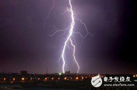
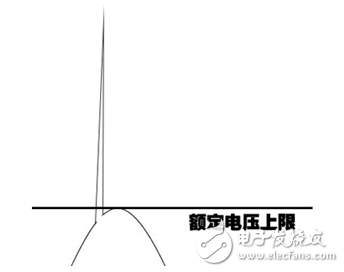
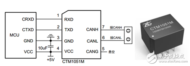
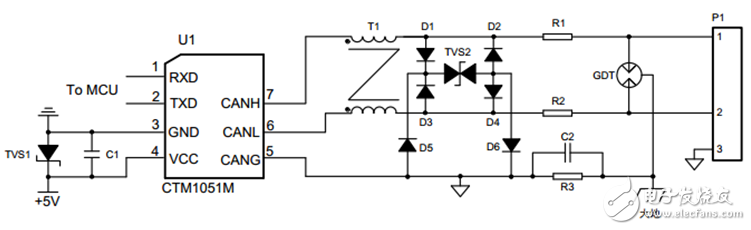
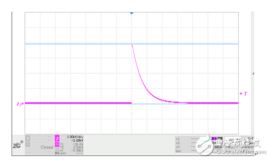
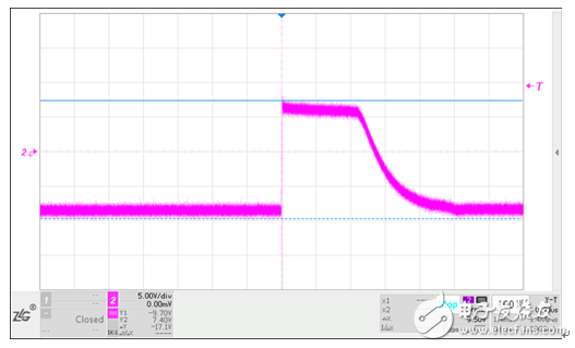
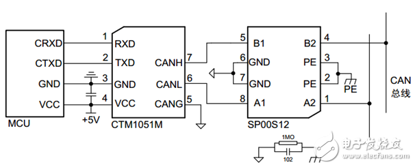
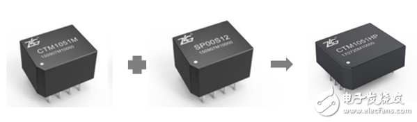
CAN-bus originated from the automotive bus and is now widely used in industrial environments where the environment is complex. Therefore, the necessary bus protection is an important guarantee for the safety of the motherboard and equipment. Today, I will talk about the lightning protection design of CAN bus. In a broad sense, lightning protection contains two concepts. One is to prevent lightning and the other is to prevent surges. Lightning strike is a phenomenon in which the charge in the thundercloud is instantaneously released. It can cause high-energy, transient electric and magnetic fields around. Surge includes surge current and surge voltage. It refers to the phenomenon that the normal working voltage and current appear in the circuit instantaneously. As shown in Figure 1, the lightning strike can be divided into direct lightning strike and non-direct lightning strike. The direct lightning strike is the direct action of lightning. On the object, the non-direct lightning strike is caused by the electromagnetic field to induce the electromotive force and the current to act on the object, both of which can generate surge voltage and surge current. Figure 1 voltage surge The CAN bus physical layer transmission medium is generally a twisted pair of copper, which is susceptible to electromagnetic field interference. The CAN transceiver is a weak component and has no resistance to the impact of voltage and current. Therefore, the lightning protection design of the complex industrial field CAN bus is necessary. CAN bus lightning protection should start from two aspects, one is the CAN transceiver, that is, interface protection. The second is the physical medium, that is, conduction protection. The main ideas of protection are shielding interference, providing venting channels, and isolation protection. CAN interface protection is generally applied to the transceiver plus isolation protection devices, such as optocouplers, magnetic couplings and so on. For easy interface design, we can use an integrated transceiver module. The modular product environment is more adaptable than a single transceiver chip. Figure 2 shows an ultra-small, isolated CAN transceiver module that can be mounted to the CAN bus and has an isolated withstand voltage of up to 2500 VDC. Figure 2 Isolated CAN transceiver module and application circuit As a rule of thumb, isolated modules require a higher level of protection circuitry to protect the module from damage and reliable communication of the bus when it is susceptible to high-energy lightning strikes. Commonly used devices are GDT, TVS, and common mode inductors. As shown in Figure 3, the GDT is placed at the forefront of the interface to provide first-level lightning surge protection. When lightning strikes and surges occur, the GDT instantaneously reaches a low-resistance state, providing a bleed-out channel for instantaneous large currents, and clamping the voltage between CAN_H and CAN_L within a range of twenty-five volts. The back-end TVS provides second-level surge protection, and specific specifications can be selected according to requirements. Figure 3 High-protection CAN interface circuit Although the above recommended interface circuit can provide effective protection, it needs to introduce more electronic devices, which means that the interface circuit will occupy more PCB space, and if the device parameters are not properly selected, it is easy to cause EMC problems. Is there a more concise protection design? Optional introduction of professional surge suppressors, this small-volume module with potting material, with a high degree of protection. Taking the SP00S12 module as an example, it can meet the IEC/EN61000-4-5 ±4KV surge level requirements. It can be used in various signal transmission systems to suppress harmful signals such as lightning strikes, surges, and overvoltages, and protect the signal ports of equipment. It is very suitable for surge protection in communication fields such as CAN and RS-485. Taking the common mode surge test as an example, a 4KV, 1.2/50μs surge voltage is applied to the SP00S12 input (Figure 4), and the test voltage drop at the output has been reduced to 17.1V (Figure 5). Figure 4 Input voltage waveform 4KV Figure 5 output terminal waveform voltage 17.1V Figure 6 shows a CAN node circuit design. Adding SP00S12 between the transceiver and the CAN bus allows the CAN signal port to easily meet the surge level requirements of IEC61000-4-5 ±4KV. Figure 6 Application of surge suppressor In addition, we have a better choice, as shown in Figure 7. The integrated high-surge protection isolated CAN transceiver can completely replace the combination of isolated CAN transceiver and surge suppressor. This solution will simplify circuit design, save PCB space, and reduce product cost. It protects against 4KV surges and 15KV of static electricity while also providing excellent EMC characteristics. Figure 7 Minimal isolation scheme Conduction protection is mainly carried out on the transmission line. The data transmission medium of the CAN bus is generally a twisted pair. Its main function is to resist low common mode interference, but in the face of surges, lightning strikes, etc., there is not only protection, but it is easy to cause damage to the node equipment. Therefore, buses with outdoor environment, long transmission distance, and multi-node device characteristics must be equipped with bridges and repeaters for isolation protection, as shown in Figure 8. When the user's CAN bus is subjected to strong interference and causes a crash or damage, after the series of products are connected, the interference protection device can be isolated for normal operation. Excellent bridge and repeater with 2500VDC, ±8KV electrostatic rating protection. Figure 8 Bridge protection scheme Is there a way to completely solve the hidden danger caused by lightning strikes? The answer is yes, as long as the transmission of data does not rely on electrical signals, the danger of lightning strikes can be completely isolated. We can use optical signals for the outdoor part of the CAN bus or the part that is susceptible to interference. This method has been widely used in high-speed railways, subways, coal mines, medical, aerospace, building security, elevator control and other occasions. Figure 9 CAN to fiber protection solution
Metal Film resistor is Film resistor (Film Resistors) of a kind.It is the high temperature vacuum coating technology will be closely attached to the porcelain nickel chromium alloy or similar bar surface skin membrane, after debugging cutting resistance, in order to achieve the final requirements precision resistance, then add appropriate joint cutting, and on its surface coated with epoxy resin sealing protection.As it is a lead resistance, it is convenient for manual installation and maintenance, and is used in most household appliances, communications, instruments and instruments.
Metal Film Resistors,2W Metal Film Resistors,3W Metal Film Resistor,5W Metal Film Resistor YANGZHOU POSITIONING TECH CO., LTD , https://www.yzpstcc.com