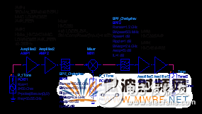
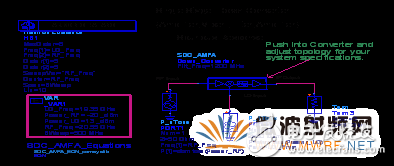
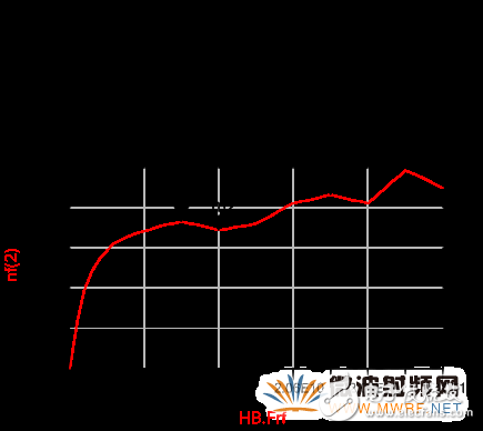
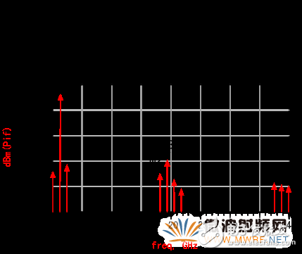
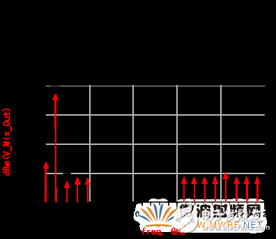
In the 21st century, with the comprehensive information and the huge global demand for personal multimedia traffic and seamless coverage, satellite communications have become one of the most important communications methods in the world today, and it is playing an increasingly important role. With the shortage of low-frequency spectrum resources and the shortage and congestion of GEO satellite orbit resources, it has been unable to meet the needs of many applications such as high-speed and broadband. Since the satellite communication system above the Ka band has the features of wide bandwidth, less interference, and small device size, it is increasingly used in satellite communications and various forms of satellite ground stations. At present, in the domestic ground relay communication system, the technology of Ka-band transmission and reception equipment is relatively mature. However, there are still gaps in the research and development of the transceiver equipment for satellite communications ground stations. Therefore, the development of key technologies and key equipment for radio frequency units in Ka-band satellite communications ground stations will not be delayed. In the study of key technologies for Ka-band terrestrial station radio frequency units, the development direction is to provide outdoor units with small size, light weight, low cost, and high reliability for fixed stations and mobile stations according to demand. The terrestrial station RF unit consists of a transmitting unit and a receiving unit. The ground station receiving unit introduced in this paper is the downlink channel part matched with the Ka-band RF transmitting unit. Figure 1 is a block diagram of the receiving unit channel and the RF signals from the 20.3 GHz to 20.8 GHz of the Ka-band ground station antenna duplexer receiving output terminal. It is amplified by a low-noise amplifier (LNA) and then inserted into a band-pass filter with a band of 20.3 to 20.8 GHz. This band-pass filter has strong suppression characteristics for the image frequency and other out-of-band noises. Then, a single-balanced mixing is performed with the 19.35 GHz local oscillator output from the Ka-band receiving phase-locked local oscillator, and the difference signal is an L-band intermediate frequency signal of 950 MHz to 1 450 MHz, and the pass band is 950 MHz to 1 450 MHz. A band-pass filter of MHz filters out various combinations of interference frequency signals, and then outputs them to an indoor unit (IDU) after being amplified by an L-band intermediate frequency amplifier. Fig. 1 Block diagram of reception channel of Ka-band satellite communication ground station According to the design scheme of the Ka band receiver unit, the main technical indicators of the known system are: 1) Input frequency range: 20.3 GHz to 20.8 GHz 2) Output frequency range: 950 MHz to 1 450 MHz 3) LNA noise figure: ≤2.5 dB 4) Image rejection: ≥60 dB 5) Spurious output: £-50 dBc (500 MHz inband) £-60 dBc (500 MHz out of band) With the rapid development of semiconductors and integrated technologies, the degree of integration of equipment is getting higher and higher. Low-noise amplifiers, mixers, and other integrated modules that already meet the requirements in the Ka-band can be directly applied to the system. Therefore, the design ideas of miniaturization, modularization, and generalization in the Ka-band receiver unit design process are always in place. In the system design, the key parts are selected by the corresponding monolithic integrated (MMIC) module, so the development of the system saves time and ensures the maintainability of the equipment, and improves the reliability at the same time. The key component in the receiving unit is the low noise amplifier, which has the characteristics of low noise figure, high gain, and large dynamic range. Comprehensive consideration of the use of the Triqunt Division's low-noise integrated amplifier TGA1319A-EPU; followed by single-side down-conversion mixer using HitTIte's monolithic integrated balanced mixing module HMC260; IF amplifier also uses a corresponding integrated module. In order to enable the imager and other out-of-band spurs produced by the mixer to be well suppressed, the input bandpass filter uses an E-faced waveguide metal diaphragm bandpass filter with strong out-of-band rejection. The circuit structure of the Ka-band receiver unit is shown in Figure 2. Figure 2 Receive Channel Circuit Diagram 4.1 Receiver Unit Topology Circuit Before the equipment enters the substantive design and development, the system is simulated and optimized using EDA software. Refer to the main technical specifications of the receiving unit and the selected devices. The ADS microwave design software was used to simulate and optimize the channel part of the receiver unit. The simulation topology circuit of the receiving unit is shown in Fig. 3. According to the topology circuit, the corresponding SimulaTIon Controller is selected to perform simulation and optimization on the main indicators of the receiving channel, and the simulation results are obtained. Figure 3 Receive Channel Simulation Topology Circuit 4.2 Noise Figure Simulation The noise figure is the total degree of deterioration of the signal-to-noise ratio at the input of the receiving system between the input and the IF amplifier. It is also a measure of the quality factor of the design of the receiving unit. The design of a good receiving unit is to obtain the best signal-to-noise ratio at its output as much as possible. It directly affects the communication quality of the receiving system. The receiving unit is composed of multiple components such as amplifiers, mixers, filters, and IF amplifiers. For the cascaded network, the noise coefficient is calculated as It can be seen that the noise coefficient of the receiving unit mainly depends on the noise figure of the pre-low noise amplifier. Because the integrated amplifiers APM1 and APM2 (see Figure 2) have a gain of about 40 dB, the noise effects of other components in the system are negligible. The noise coefficient of the receiving unit was simulated. In the simulation curve of Figure 4, the noise figure in the operating frequency band was ≤ 2.16 dB, which satisfied the system requirements. Figure 4 Noise figure curve 4.3 Image Rejection and Spurious Output Simulation The input signal of the receiving unit is amplified by each stage amplifier and then enters the mixing module. After the mixing, it will generate several spurious frequencies, but the most noteworthy one is two frequencies, one is the sum frequency ω+=ωL+ωs; the other is the mirror Frequency ωk=2ωL-ωs. This frequency is in mirror image with respect to the local oscillator. However, in comparison, the image frequency is the closest to the frequency signal, so it is easy to fall within the signal band and affect the signal. In the microwave receiving system, image rejection is a very important technical problem. Good image rejection can avoid noise degradation and reduce external image interference. A common way to implement single-sideband reception is to connect a band-pass filter at the mixer signal input to suppress the mirrored input signal. The waveguide-type E-faced metal-film bandpass filter with strong out-of-band suppression can effectively suppress the interference between the image frequency and external clutter. The simulation results show that the image rejection of the receiving unit is ≥70 dB and the spurious output is -68 dB. The simulation results are shown in Figure 5 and Figure 6, respectively. Figure 5 Image rejection curve Figure 6 Spurious output curve Through the simulation design, it can be seen that the technical indicators of each component selected in the design of the receiving unit are matched with the requirements of the receiving channel. The technical indicators can meet the system requirements, and the feasibility of the simulation results is also verified during the development of the equipment. Therefore, by using EDA software to simulate and design the system, we can judge the rationality and advantages of the technical indicators of the communication system, make the communication system play the maximum benefit, and at the same time make some processes that could not be tested to be verified in the simulation. It provides an important basis for the successful development of equipment, thus effectively avoiding detours and time-consuming in the process of equipment development. In Ka-band terrestrial station receiving channel, a variety of amplification and frequency conversion integrated devices are reasonably selected to realize the modularization, miniaturization and generalization of the channel. For different requirements of the ground station, the appropriate exchange of the corresponding device can meet its requirements.
Barium titanate lead-free piezoelectric
ceramics are important basic materials for the development of modern science
and technology, which was widely used in the manufacture of ultrasonic
transducers, underwater acoustic transducers, electroacoustic transducers,
ceramic filters, ceramic transformers, ceramic frequency discriminators, high
voltage generators, infrared detectors, surface acoustic wave devices,
electro-optic devices, ignition and detonation devices, and piezoelectric
gyroscope and so on.
Application: military, ocean, fishery, scientific research,
mine detection, daily life and other fields.
Piezo Disc,Piezo Rod,Lead Free Piezo Rods,Lead Free Piezo Discs Zibo Yuhai Electronic Ceramic Co., Ltd. , https://www.yhpiezo.com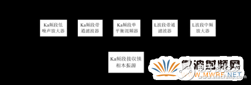


1 Introduction