The RF connector is connected to a coaxial cable, microstrip line or other RF transmission line to enable the electrical connection of the transmission line, separation or the transfer of different types of transmission line. It belongs to mechatronics products and acts as a bridge. The model of the RF coaxial connector consists of two parts: the main code and the structure code, separated by a dash "-". The main code name of the main code name RF connector adopts the internationally-used main code name, and the naming of different structural forms of specific products is specified by detailed specifications. The structure of the structure code RF connector. 1) According to the connection interface structure is divided into: Bayonet type (internal bayonet, outer bayonet): BNC Threaded (right-handed, left-handed): L29 (7/16), N, F, TNC, SMA, SMC, SSMA, SSMB, FME, L9 (1.6/5.6), 7mm, 3.5mm, 2.4mm, K (2.92mm), 1.85mm, 1mm; Push-in (in-line, self-locking): SMB, SSMB, MCX, MMCX, SMP, SMI, BMA, SAA; Flange connection: 2) Classified by size: Standard type: UHF, N, 7/16, 7mm; Small: BNC, TNC; Ultra-small: SMA, SMB, SMC, MCX, BMA, SAA, 3.5mm; Micro: SSMA, SSMB, MMCX, 2.4mm, K (2.92mm), 1.85mm, 1mm; Impedance: Almost all RF connectors and cables are standardized to an impedance of 50 Ω. The only exception is that 75Ω systems are commonly used for cable TV installations. It is also important that the RF coaxial cable connector has the characteristic impedance of the matched cable. If this is not the case, a discontinuity can be introduced and lost. VSWR (Voltage Standing Wave Ratio): Ideally, it should be united, good design and implementation can keep VSWR below 1.2 in the range of interest. Frequency range: Most RF operations now range from 1 to 10 GHz, so connectors must have low losses in this area. For the case of 10 GHz or more - there is a lot of work, now in the range of 10 to 40 GHz - there are connectors that are newer. They are expensive because it is the cable itself. Insertion loss: This is the connector loss in the frequency range of interest. Losses are usually between 0.1 and 0.3 decibels. How critical the watts per watt (or watts) is in most designs, even such small losses must be minimized and factored into the link loss budget. It is especially important at low noise fronts when signal strength and signal-to-noise ratio are low. Operating cycle: How many connection/disconnection cycles can be connected and still meet the specifications? This is usually in 500 or 1000 cycles. Threaded connectors, supplier-specified tightening torques are an important factor in maintaining performance and reliability. Power: Power handling is determined by two resistive losses (heating) and insulation breakdown. While even decades of design are primarily pre-processing tens of watts, today's design community focuses on low-power devices such as cell phones, picocells and femtocells, video interfaces, RF and gadgets. These are in the sub 1W range, so the connector can be much smaller and its rated power is a smaller constraint.
Sensor Cable Assembly
With the fast growth of intelligent electrical appliances, electric vehicle and industrial automation, more and more sensors applied to make different sensor cable assemblies. Manufactures show much high requirements for the sensor function and quality. As one professional sensor assembly solution provider, Feyvan Electronics has rich experience on temperature sensor manufacturing.
Sensor Cable Assembly,Sensor Harness,Sensor Cable,Cable Harness Assemblies Feyvan Electronics Technology Co., Ltd. , https://www.fv-cable-assembly.com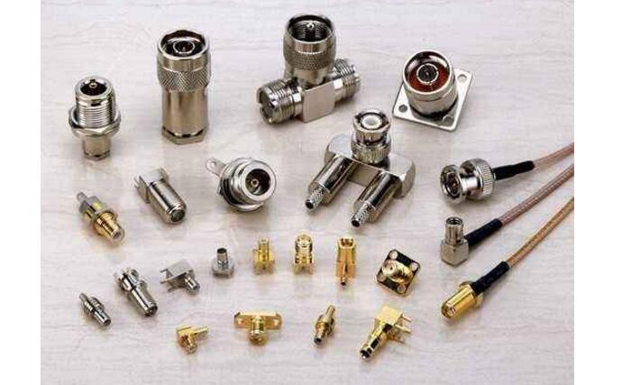
First, RF connector introduction