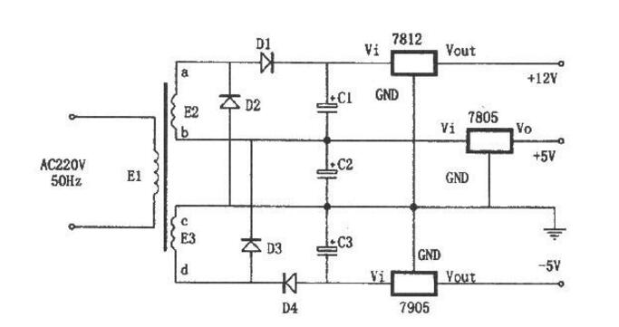
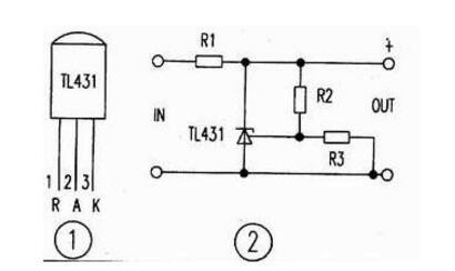
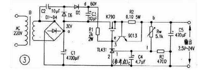
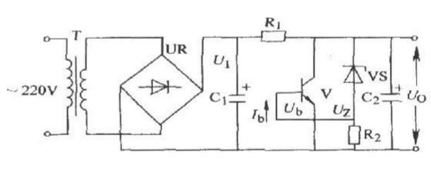
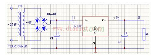
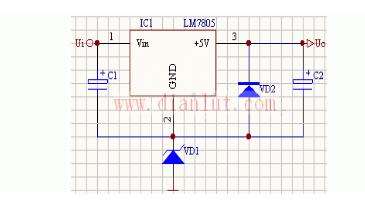
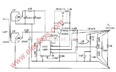
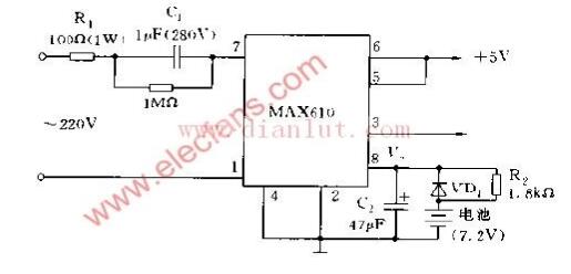
Stabilized voltage supply is an electronic device that can provide stable AC or DC power to the load, including AC regulated power supply and DC regulated power supply. When the grid voltage or load appears to fluctuate instantaneously, the regulated power supply compensates the voltage amplitude with a response speed of 10-30ms, which makes it stable within ±2%. This article mainly introduces the circuit diagram of the regulated power supply and the schematic diagram of the 5v regulated power supply circuit, etc., and follow the small series to understand. 1. Special linear regulated power supply consisting of 7805, 7905, 7812 As shown in the figure is a special power circuit. Although simple, the circuit can generate three sets of DC voltages from two identical secondary windings: +5V, -5V, and +12V. Its characteristics are: D2 and D3 are connected between the two sets of AC power supplies E2 and E3, which play the role of full-wave rectification. Second, use TL431 as a high-power adjustable power supply The precision voltage reference ICTL431 is a T0-92 package as shown in Figure 1. Its performance is that the output voltage can be continuously adjusted up to 36V, the operating current range is as wide as 0.1100mA, the dynamic resistance is typically 0.22 ohms, and the output clutter is low. Figure 2 shows a typical application of the TL431, in which the output voltages of the 3 and 2 pins are V=2.5 (R2 X R3) V/R3. If you change the resistance of R2, you can change the output reference voltage. Fig. 3 is a stabilized power supply with a large output current (about 6A) and a simple and safe circuit using the voltage reference and driving the external field effect transistor K790 as an adjusting tube. working principle As shown in Figure 3, the 220v voltage is stepped down by transformer B, D1-D4 rectified, and C1 filtered. In addition, D5, D6, C2, C3 form a voltage doubler circuit (making Vdc=60V), Rw and R3 form a voltage dividing circuit, T1431 and R1 form a sampling and amplifying circuit, 9013 and R2 form a current limiting protection circuit, and the field effect transistor K790 is adjusted. Tubes (which can be used in parallel) and C5 are output filter circuits. The voltage regulation process is: when the output voltage is lowered, the potential at point f is lowered, and the voltage at point e is increased by internal amplification of T1431. After the adjustment of K790, the potential at point b is increased; conversely, when the output voltage is increased, the potential at point f is increased. The potential at point e decreases, and after adjustment by K790, the potential at point b decreases. Thereby the output voltage is stabilized. When the output current is greater than 6A, the transistor 9013 is turned off, so that the output current is limited to 6A, thereby achieving the purpose of current limiting. This circuit has 2W for resistor R1 and 5W for R2. There are no special requirements for other components. The component parameters are shown in Figure 3. A 5V output power circuit composed of 7805 The typical application circuit of the 78XX series integrated voltage regulator is shown in the figure below. This is a regulated power supply circuit that outputs positive 5V DC voltage. The IC uses an integrated voltage regulator 7805, C1 and C2 are input and output filter capacitors, respectively, and RL is a load resistor. When the output power is large, the 7805 should be equipped with a heat sink. The picture shows an application circuit that increases the output voltage. The Zener diode VD1 is connected in series between the pin of the 78XX regulator and the ground, so that the output voltage Uo can be improved. The output voltage Uo is the sum of the output voltage of the 78XX regulator and the regulated voltage of the Zener diode VC1. VD2 is the output protection diode. Once the output voltage is lower than the VD1 regulation value, VD2 turns on and bypasses the output current to protect the 7800 regulator output stage from damage. The picture shows the application circuit whose output voltage can be adjusted within a certain range. Due to the role of the R1, RP resistor network, the output voltage is increased, and the magnitude of the increase depends on the ratio of RP to R1. Adjust the potentiometer RP to adjust the output voltage within a certain range. When RP=0, the output voltage Uo is equal to the output voltage of the 78XX regulator; when the RP is gradually increased, Uo is gradually increased. Second, the output 20A 5V regulated power supply circuit composed of A723 The figure shows an output 20A/5V regulated power supply circuit composed of A723. The external transistor of this circuit makes the output current reach 20A. If the output voltage exceeds 6V, the thyristor VS operates to prevent overvoltage generated when the output terminal is short-circuited. Below 5V, the input voltage is about 13V, the working power supply of A723 is provided by auxiliary power supply, the operating current of constant current protection loop is about 30A, the output voltage can be adjusted from 4.92 to 5.09V, and multiple transistors in parallel are used in the circuit. Pay attention to the current sharing problem. Third, MAX610 uninterrupted 5V power supply circuit In the figure is an uninterrupted 5V power supply circuit. When the mains supply is powered, V is slowly charged to the 7.2V battery through R2. When the mains supply is stopped, the battery is powered by the diode VD1. The MAX610 can continuously supply 5V voltage output until V+ is approximately 5.8V. Even if the battery voltage drops to 6.5V. Heating Pad For Feet,Heating Pad For Foot,Foot Heating Pad,Cordless Foot Warmer Ningbo Sinco Industrial & Trading Co., Ltd. , https://www.newsinco.com