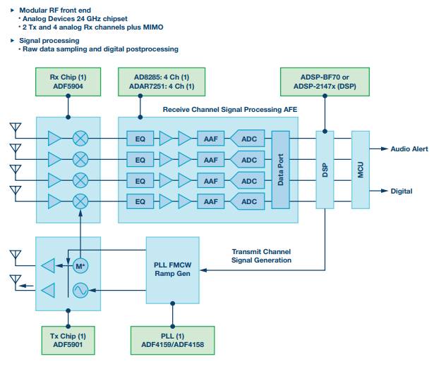
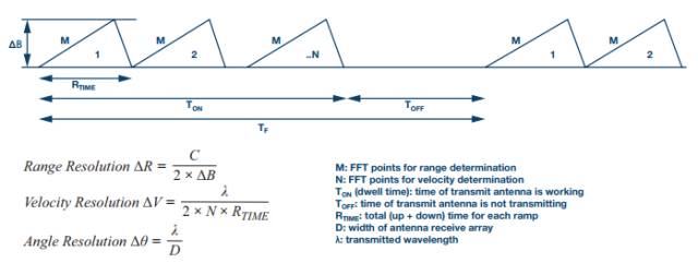
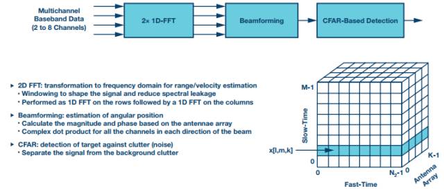
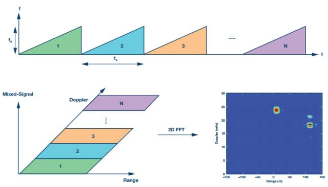
24 GHz silicon-based millimeter-wave radar technology is enabling a new generation of real-world, increasingly non-contact smart sensors for mass-market applications such as automotive, drone, pan-industrial and consumer applications. ADI's new 24 GHz radar products deliver outstanding performance and high integration, making them small, low-cost, and easy-to-use ultra-low power solutions for applications such as physical inspection, tracking, safety control, and collision warning systems. With the advent of new RF radar sensor applications, many companies looking to quickly complete the evaluation, design and manufacture of radar sensor solutions face a number of new development challenges. ADI's 24 GHz radar system-level prototyping solution (called DemoRAD) (Figure 1) enables hardware and software application development across the entire system reference design. Figure 1. 24 GHz DemoRAD Platform Solution The 24 GHz DemoRAD system is a novel microwave radar evaluation platform that provides an out-of-the-box software example that easily activates the radar sensor in minutes. DemoRAD enables rapid prototyping of radar sensor products to measure real-time information such as target/object presence, motion, angular position, speed, and sensor range. The system hardware solution includes an RF antenna and a complete RF to baseband signal chain (ADF5904 (receive), ADF5901 (transmit), ADF4159 (PLL), ADAR7251 (AFE)), which also includes ADI's ADSP-BF707 DSP (digital Signal Processor) Quickly connect to a laptop/PC with an easy-to-use graphical user interface and radar algorithm software (Figure 2). Figure 2. DemoRAD RF to baseband signal chain and simplified block diagram Radar FFT and control firmware is available in the Blackfin® DSP library. The user can plug the platform system into a computer loaded with software in just a few minutes. Full software 24 GHz radar IC software support is provided using the software graphical user interface (GUI), with additional data available in the DSP radar support library and dedicated MATLAB® tools designed for radar sensors (eg 2D/) 3D radar FFT, CFAR and classification algorithms are post-processed on the PC. FMCW radar system basics Figure 3 shows the FM continuous wave (FMCW) radar wave ramp generated during radar launch and a set of important radar formulas used to define radar sensor design information. Figure 3. FMCW radar concept The distance resolution depends on the transmit carrier scan bandwidth - the higher the transmit scan bandwidth, the higher the distance speed of the radar sensor. The speed resolution depends on the dwell time and the carrier frequency - the higher the carrier frequency or the longer the dwell time, the higher the speed resolution. The angular resolution depends on the carrier frequency - the higher the carrier frequency, the better the angular resolution. Figure 4 depicts the post processing of the data captured in the ADSP-BF707. Figure 4. FMCW digital post-processing signal chain The DemoRAD system signal chain includes some basic algorithms in the DSP that are implemented for DSP FFT, beamforming, and CFAR. Basic target detection and target classification run on the host PC. DemoRAD is mainly used to collect radar signals in the time domain and frequency domain. DemoRAD does not include advanced target detection or object classification algorithms. This is an example of application-level development work, usually performed by end system developers who have a good understanding of the working environment of the radar sensor and the type of object detection required. Figure 5 shows the Blackfin ADSP-BF70x's partially optimized 2D FFT with integrated windowing to help avoid saturation, achieve higher SNR, and optimize memory layout for higher bandwidth and more efficient data processing. DemoRAD offers different modes of operation. Figure 5. Distance and Doppler frequency using two-dimensional Fourier transform FMCW radar mode In FMCW mode, the distance to a stationary target can be measured. The frequency of the target's downconverted received signal is proportional to the distance to the target. In the GUI, FFT processing can be performed to determine the frequency. Use the distance-time display option to view moving targets while the display stores multiple FMCW scans. Distance Doppler mode In the distance Doppler mode, the distance and speed of the target can be analyzed. The Doppler mode is one of the most powerful modes of operation because it can simultaneously process multiple launch ramps by evaluating a two-dimensional Fourier transform. The distance Doppler processing data is displayed in the distance Doppler map. Doppler is very powerful because it allows separation of targets with different speeds, even if the distances of these targets are the same. This is useful for multiple fast-moving targets in different directions—for example, to solve complex traffic conditions during a car moving in the opposite direction or during overtaking. Digital Beamforming (DBF) mode In DBF mode, the distance to the target and the angle to the target are displayed. The received signals from the four receive channels are used to estimate the angle of the target. The display shows the spatial distribution of the targets in the xy plane. In DBF mode, the system configuration is the same as in FMCW mode, but the processing of IF down-converted signals is different. After calculating the distance, the angle information of the target is calculated by evaluating the phase difference between the four receiving channels. In DBF mode, radar front-end system calibration is required to eliminate unnecessary deterministic phase differences between the receive channels. Each DemoRAD system has factory calibration data that is loaded when the GUI is run. The sampled IF signal is then corrected and the sensor's measurement data is evaluated. The MIMO operating principle of the DemoRAD platform is to use the two available transmit outputs on the ADF5901 and place the corresponding antennas. This produces seven receive channels to increase the angular resolution of the sensor—for example, four actual receive channels and four virtual receive channels, overlapping on one channel. The waveforms used in DemoRAD utilize the fast ramping characteristics of the ADF4159 PLL, where the rising chirp is 280μs and the falling chirp is 4 for a total of 284μs. The ADAR7251 AFE ADC acquires 256 samples or samples data on a rising edge with 1 MSPS operation. DemoRAD uses the FMCW radar to monitor object ranges and speeds up to 200 meters and resolutions of approximately 75 cm. According to the antenna array design, the horizontal (FOV) azimuth is about 120° and the pitch angle is about 15°. By combining antennas in digital beamforming (DBF), DemoRAD uses DBF to calculate angle information in the FOV. Right Angle D-sub Connector IP66 IP67 Rated
IP66 / IP67 waterproof d-sub connectors-Designed for IP Performance
ANTENK has developed IP66 / IP67 waterproof d-sub connectors that utilize a proprietary sealing technology, which maintains the same physical size and footprint as standard d-sub products.
Antenk's line of Waterproof d-sub connectors utilize an innovative sealing technology eliminating the need to redesign enclosures and PC boards when implementing IP67 design upgrades.These connectors are designed for applications that require protection from heavy spray or are exposed to short-term submersion. Connectors are available in vertical and right angle board mount types as well as solder cup for panel mount cable applications. Standard D-Subs are available in 9 pin, 15 pin, and 25 pin positions, and high density D-Subs are available in 15 pin, 26 pin, and 44 pin positions
Right Angle D-SUB Connector IP66 IP67 Rated available in
3 industry sizes/positions:Standard Density (9 pin, 15 pin, 25 pin). Right Angle D-Sub IP67 Rated,Right Angle D-Sub Waterproof,Standard Density Waterproof Right Angle D-Sub Connector, High Density Waterproof Right Angle D-Sub Connector ShenZhen Antenk Electronics Co,Ltd , https://www.antenkconn.com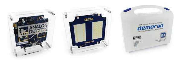

Applications of Antenk waterproof d-sub connectors:
Hand held computers, scanners, and printers that are used outdoors
Remote sensors, gauges, and data loggers that are used outdoors
Industrial and Medical equipment that is routinely subject to wash down
Transmitters and emergency beacons that are subject to temporary submersion
Gas, Electric, and Water metering systems that have embedded Smart Grid electronics
Portable electric generation equipment (Gen Sets)
Consumer and Commercial boating electronics (Radios, Scanners, Radar, DC Power Ports)
IP67 D-SUB | WATERPROOF CONNECTORS FEATURES & BENEFITS
Signal / Low Power in 6 standard size
(Standard: 9 pin, 15 pin, 25 pin; High Density: 15 pin, 26 pin,44 pin)
Combo-D / High Power in a variety of configurations:
(3W3, 5W5, 7W2, 9W4, 11W1, 13W3, 13W6, 17W2, 21W1, 21WA4)
Solder Cup, Vertical Mount & Right Angle Board Mount Options
High Reliability Screw Machined Contacts
3 amp / 5 amp / 20 amp / 40 amp Power Options
-65°C to +105°C Operating Temperature Range
Male & Female Versions
Right Angle D-sub Connector IP66 IP67 Materials
Shell: Steel with Nickel Plating.
Insulator: Glass-filled thermoplastic. U.L. rated 94V-O
(260° process temp for board applications)
Machined Contacts:
Male Pins - Brass
Plating: Gold Flash on entire contact.
IP67 Right Angle D-Sub Seal: Proprietary Information