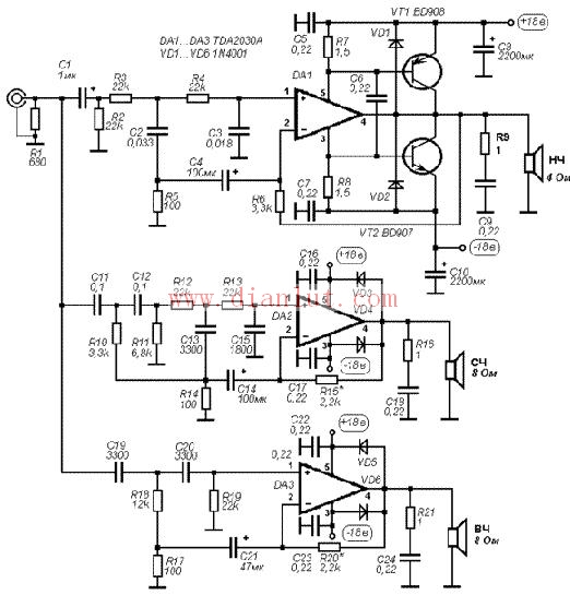
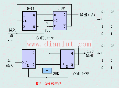
The following is the circuit diagram of the electronic three-way circuit Electronic three-way circuit As shown in the figure, the three-way circuit diagram is a relatively classic three-way circuit. The circuit components are relatively simple. Figure 2 is a 3-way circuit. It is convenient to use the JK-FF to divide by 3, and it is possible to realize the synchronous count division without adding any logic circuit. However, when D-FF is used to divide by 3, a decoding feedback circuit must be added. As shown in the decoding reset circuit shown in Figure 2, the forced counting state returns to the initial all-zero state, that is, the NOR gate circuit is used to set Q2, Q1 = " The state decoding of 11B" generates an "H" level reset pulse, forcing FF1 and FF2 to be reset at the same time (before the arrival of the pulse of the next clock input Fi), so that Q2, Q1 = "11B" state is only instantaneous as a "glitch" There is a cycle that does not affect the frequency division. This "glitch" exists only in Q1. It may cause errors in practice. It should be added with a clock synchronization circuit or a RC low-pass filter circuit to filter out, or only Q2 is used as the output. D-FF divides by 3, and can also use the AND gate to decode Q2 and Q1 to realize returning zero. Our company specializes in the production and sales of all kinds of terminals, copper terminals, nose wire ears, cold pressed terminals, copper joints, but also according to customer requirements for customization and production, our raw materials are produced and sold by ourselves, we have their own raw materials processing plant, high purity T2 copper, quality and quantity, come to me to order it! Copper Connecting Terminals,Cable Lugs Insulated Cord End Terminals,Pvc Insulated Cord End Terminal,Cable Connector Insulated Cord End Terminal Taixing Longyi Terminals Co.,Ltd. , https://www.lycopperlugs.com
