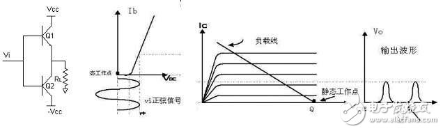
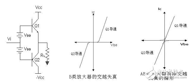
Mobile phones or other stylish portable multimedia players with beautiful melodies, wherever you go you can attract envious eyes, especially in today's consumer demand for sound is getting higher and higher, good sound design means product success Otherwise, the big and bright iPods and iPhones are the best proof of the importance of sound effects. In the process of sound design, amplifier equipment is also very important. Whether it is the traditional Class A or the currently popular Class D, different choices mean different characteristics of the product. But do you know how to choose the right amplifier for your design? Do you know how to design variously according to different types of amplifiers? If you still have misunderstandings in these issues, please read this topic carefully. Senior design engineers from IDT and senior engineers from National Semiconductor, American Credit and other manufacturers will jointly reveal the R & D problems you should master on the road of audio design. 1. Classification of Audio Amplifier The traditional digital voice playback system includes two main processes: 1. The conversion of digital voice data to analog voice signals (using a high-precision digital-to-analog converter DAC); 2 The use of analog power amplifiers to amplify analog signals, such as Class A, B Class and Class AB amplifiers. Since the early 1980s, many researchers have devoted themselves to the development of different types of digital amplifiers. Such amplifiers directly achieve power amplification from digital voice data without the need for analog conversion. Such amplifiers are often referred to as digital power amplifiers or Class D amplifiers. 1. Class A amplifier The main characteristics of the class A amplifier are: the operating point Q of the amplifier is set near the midpoint of the load line, and the transistor is turned on during the entire period of the input signal. The amplifier can work in single tube or push-pull operation. Because the amplifier works in the linear range of the characteristic curve, the transient distortion and alternating distortion are small. The circuit is simple and debugging is convenient. However, the efficiency is low, the power consumption of the transistor is large, the theoretical maximum power is only 25%, and there is a large nonlinear distortion. Due to the low efficiency, the design is basically no longer used. Figure 1: Class A amplifier 2. Class B amplifier The main characteristic of Class B amplifiers is that the static point of the amplifier is at (VCC, 0). When there is no signal input, the output end consumes almost no power. In the positive half cycle of Vi, Q1 is turned on and Q2 is cut off, and the output terminal is a positive half-cycle sine wave; in the same way, when Vi is a negative half-wave sine wave (as shown by the dotted line in the figure), it must work with two tubes. It is characterized by high efficiency (78%), but because the amplifier has a section of operation in the nonlinear region, the disadvantage is that the "crossover distortion" is large. That is, when the signal is between -0.6V ~ 0.6V, Q1 Q2 can not be turned on and caused. Therefore, this type of amplifier is gradually abandoned by designers. Figure 2: Class B amplifier 3. Class AB amplifier The main characteristics of class AB amplifiers are: the conduction time of the transistor is slightly longer than half a cycle, and two tubes must be used for push-pull operation. Crossover distortion can be avoided. Alternating distortion is large, which can offset even harmonic distortion. It has the characteristics of high efficiency and low transistor power consumption. When the signal is between -0.6V and + 0.6V, in order to turn on Q1 and Q2, add two bias voltages between the VBE of Q1 and Q2 to make the input signal between +-0.6V , Q1, Q2 can also be linearly amplified. This can not only achieve higher power efficiency, but also improve the crossover distortion of the class B push-pull amplifier. In theory, the maximum power of 78.5% can also be reached, but in fact the maximum power of about 70% may be affected by the output stage topology and the output stage slash, under typical listening conditions (about 30% of full power) ), The efficiency of the power amplifier is about 35%. Figure 3: Class AB amplifier 4. Class D amplifier Class D (digital audio power) amplifier is an input analog audio signal or PCM digital information converted into PWM (pulse brightness modulation) or PDM (pulse density modulation) pulse signal, and then use PWM or PDM pulse signal to control the large Power switching devices turn on / off audio power amplifiers, also called switching amplifiers. It has outstanding advantages of high efficiency. The digital audio power amplifier also appears to be a one-bit power digital-to-analog converter. The amplifier consists of four parts: input signal processing circuit, switching signal forming circuit, high-power switching circuit (half bridge type and full bridge type) and low-pass filter (LC). Class D amplifier or digital amplifier. It uses very high frequency transfer switch circuit to amplify the audio signal. 1. Has a very high efficiency, usually can reach more than 85%. 2. The small size can save a lot of space compared with the analog amplifier circuit. 3. Switch on without cracking noise 4. Low distortion and good frequency response curve. There are few peripheral components, which is convenient for design and debugging. As shown in Fig. 4, compared with the PWM signal, the PDM signal has no fixed operating frequency, and it modulates the input audio signal into a group of PDM signals with the same pulse width but different frequencies, which effectively improves the EMI problem caused by the PWM. At present, there are not many products on the market. Figure 4. This simplified functional block diagram shows the structure of a basic half-bridge Class D amplifier. Figure 5. The pulse width of the output signal is proportional to the amplitude of the input signal. PWM (Pulse Width ModulaTIon) Class A, Class B and Class AB amplifiers are analog amplifiers, and Class D amplifiers are digital amplifiers. Class B and AB push-pull amplifiers are more efficient and less distorted than class A amplifiers, power amplifier transistors consume less power, and have better heat dissipation, but class B amplifiers have poor switching characteristics during the transition between the transistor's on and off states. Or alternate distortion occurs due to improper selection of circuit parameters. The Class D amplifier has high and low distortion and good frequency response curve. The advantages of fewer peripheral components. Class AB amplifiers and Class D amplifiers are the basic circuit forms of current audio power amplifiers. Fiber Optic Cable Channel Assembly
An optical fiber trough is a cable trough for laying soft optical fibers. Material general points: flame retardant engineering plastics, aluminum alloy, steel several. Width is 120mm, 200mm, 240mm, 300mm, 340mm, 400mm, height is generally 100mm. Other sizes can be customized by manufacturers in case of mass purchase. Generally, it is used for wiring in indoor machine rooms.
Classification of optical fiber troughs
1. Plastic optical fiber trough
Plastic fiber groove is a new product developed according to the requirements of high standard machine room construction, absorbing the advantages of foreign products combined with China's national conditions. The groove body and fiber outlet and other accessories are made of high-quality flame retardant materials, good integrity, simple installation, corner corner protection, to ensure that the bending radius of the fiber is greater than 40mm; The fiber outlet is made of flame-retardant plastic and protected with rounded corners. It can be moved freely in the tank to facilitate fiber laying in the appropriate position.
2. Aluminum alloy optical fiber trough
Aluminum alloy fiber groove is designed and manufactured for the various environments and places used in fiber groove, as well as the wishes of customers at home and abroad. It is a new type of fiber groove required by high standard machine room.
The main channel and the column channel are assembled by special aluminum alloy profiles, the surface is chemically treated, and the bottom plate of the channel body is often aluminum plastic plate, which is neat and beautiful. The optical fiber trough can also be separately installed on the cable tray.
Fiber Optic Cable Channel assembly is an essential component of fiber optic networks. It is used to protect and manage fiber optic cables, ensuring that they are properly installed and maintained. This assembly is designed to protect fiber optic cables from environmental factors such as moisture, dust, and temperature changes, which can cause signal loss and degradation.
Fiber Optic Cable Channel Assembly,Optic Fiber Cable Channel,Fiber Optic Channel,Fiber Optic Cable Channels Rayhot Technology Group Co.,Ltd , https://www.cnrayhot.com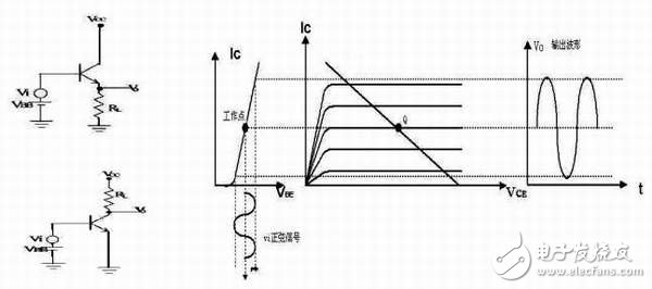
A fiber optic cable channel assembly typically consists of a channel, a cover, and mounting hardware. The channel is a long, narrow structure that is designed to hold multiple fiber optic cables. It is usually made of metal or plastic and can be mounted to a wall or other structure. The cover is used to protect the cables from external factors and can be made of a variety of materials, including plastic, metal, or fiberglass.
The mounting hardware is used to secure the channel and cover to a wall or other structure. It typically includes screws, bolts, or other fasteners that are designed to hold the assembly in place. Some fiber optic cable channel assemblies also include cable ties or other devices that are used to secure the cables inside the channel.
Fiber optic cable channel assemblies are used in a variety of applications, including telecommunications, data centers, and industrial environments. They are particularly useful in environments where space is limited or where cables need to be protected from external factors. For example, in a data center, fiber optic cable channel assemblies can be used to organize and protect cables running between servers and other equipment.