A seemingly simple design, in fact, full of the efforts of several engineers and day and night, this design needs to undergo rigorous and repeated evaluation, before it can be launched on the market. TI Designs reference design library, sincerely for you to create a classic! Looking for more reference designs? Go to the TI Designs reference design library and have the design you want! TI Designs Design Library will introduce a series of reference design selections, including industrial, medical, automotive electronics, factory automation and control, building automation, personal electronics and other applications, updated weekly, don't miss it! Now, let's take a look at the first recommendation of the "Automotive Electronic Reference Design" in the first issue! To learn more, click here for the original introduction to this reference design. Design overview This design is a start-up simulator that produces three different start-up pulses to test automotive systems up to 50W. The microcontroller sets the output voltage of the synchronous buck in the 2-15V range based on the programming curve. The output current range is 3.3-25A. It is a complete system that provides all the information needed to make the device. Design system block diagram (click here to download the complete block diagram) >>Learn more  Design features: Transient function Transient protection with up to 62V peak input voltage for design flexibility The device responds to line transients almost immediately, with output regulation above 1% Small size Voltage tracking reduces external components and saves board space Application note Logic devices support live insertion, partial shutdown mode, and post-drive protection Minimize losses in power applications >>Learn more  Design documentation (click to download full design resources) >>Learn more   Core design device: model description Related documents Free sample CSD18503Q5A 40V N-Channel NexFETTM Power MOSFET, CSD18503Q5A LM2841 300 mA up to 42V input step-down DC/DC regulator in ultra-thin SOT-23 package LM2841-Q1 300 mA up to 42V input step-down DC/DC regulator in ultra-thin SOT-23 package SN74LVC1G14 Single Schmitt trigger reverser TPS40170 4.5V to 60V Wide Input Synchronous PWM Buck Controller
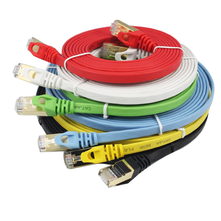
CAT6A Flat Patch Cable, A Flat cable design helps improve the look of your home or office. Flat cables are super flexible and can be run under the carpet or bent through corners or into desks.
A double stranded DU line from the latest BAI in ISO/IEC 11801 class 6A /F standard 1. It is mainly used for the application and development of ten thousand ZHI bit Ethernet DAO network technology.CAT6A is an shielded twisted pair , thus providing a combined attenuation to crossposition ratio of 500MHZ, more than twice that of CAT6 and Cat5e patch cable, with a transmission rate of up to 10Gbps. In the CAT6A Ethernet Cable, each pair has a shield layer, and four pairs of wires together have a common shield layer.
Cat6a Flat Ethernet Cable,Nylon Braided Shielded Ethernet Cable,Cat6a Flat Cable,Nylon Braided Network Cable Cat7 Shenzhen Kingwire Electronics Co., Ltd. , https://www.kingwires.com![[Automotive Electronic Reference Design Selection-1] Startup Simulator for Automotive Applications](http://i.bosscdn.com/blog/04/1T/9B/93_0.png)
![[Automotive Electronic Reference Design Selection-1] Startup Simulator for Automotive Applications](http://i.bosscdn.com/blog/04/1F/1J/M_0.png)
![[Automotive Electronic Reference Design Selection-1] Startup Simulator for Automotive Applications](http://i.bosscdn.com/blog/11/34/06/31A-2.png)
In terms of physical structure, the additional shielding layer makes the CAT6A have a larger diameter.Another important difference is its ability to connect hardware. The parameters of the cat7 of systems require that all pairs of wires provide at least 60DB of integrated proximal winding at 600MHZ.The cat5e systems only require 43DB at 100MHZ and 46DB at 250MHZ for the CAT6.
