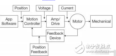
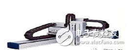
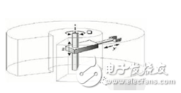
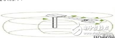
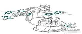
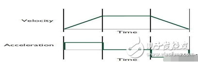
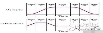
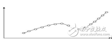
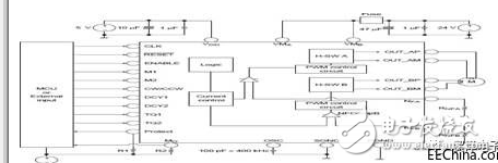
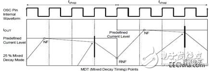
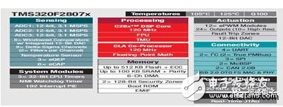
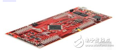
The robot's motion control method seems to be very simple: there is a driver's support for the end effector to reach the specified position quickly and accurately, and of course some adjustments are involved, as with all engineering decisions, depending on the optimal outcome of the given application. Level setting. The selection of robot motion control systems ranges from basic dedicated function ICs to highly integrated and highly flexible MCUs with integrated auxiliary and support functions. Nowadays, the control of complex robot arms, regardless of their size and power, requires multi-axis synchronization management to achieve motion control. Modern electronics - motors, power switching devices (MOSFETs, IGBTs), device drivers, control systems (now digital, formerly analog control), feedback sensors - make precise motion control easier than it was a few years ago (As shown in Figure 1). At the same time, however, the system performance needs have also increased significantly, so the construction of the entire project is now quite difficult. Figure 1: Robot-based motion control system, including algorithmic execution functions, motor drive, power supply, feedback loops; mechanical drives, motors and sensors (in most cases); critical node settings for voltage and current measurement and control. No matter how a real situation is inevitable: the robot is a large mechanical system, so this part of the actual system must be an important part of the control loop. This involves gear bounce, mechanical error, vibration, motor performance, rotational inertia, momentum, bending of mechanical structures, load changes, and more. It is therefore important to choose which type of motor to use - for medium/low power applications, we usually choose between a brushless DC motor and a stepper motor. Another important decision is sensor feedback. Most robotic applications use some type of feedback sensor to accurately measure the end effector's stroke, acceleration, and acceleration (repeated: speed is the derivative of travel versus time, and acceleration is the derivative of speed versus time). The feedback sensor can be a Hall effect sensor, an automatic synchronizer or an optical encoder. Due to the mechanical problems mentioned above, although it is easy to mount the encoder on the motor, it may not be able to provide accurate data for the end effector for application accuracy requirements. Therefore the sensor needs to be mounted closer to the load end. Some motion control applications have no sensors, which reduces cost and mechanical complexity. Without sensor feedback, sensorless application-oriented control (FOC, also known as vector control) utilizes accurate synchronization of voltage and current per phase winding of the motor; then FOC uses complex frame references for real-time conversion and matrix calculations. Determine the rotational position of the motor. Eliminating the sensor reduces hardware costs, but requires more computing power and more complex programming. Many robot designs tend to use sensors because FOC does not provide the same level of confidence, feasibility, and reliability relative to direct sensor readings. Although the public tends to associate the term “robot†with mobile, life aids or assistants, most of the robotic systems in the industrial field are stationary, using a variety of robotic arms to accomplish various tasks through previous configurations. . The most common designs are as follows: • Cartesian robots, set up three linear motion axes, distributed in the X, Y, and Z planes (as shown in Figure 2). This design is primarily used for picking and placing machines, seamless applications and basic assembly. Figure 2: Cartesian robots are the easiest to understand and control, respectively equivalent to the X, Y, Z plane control • Column-type robot, all movements are limited to a circular area. It combines the linear motion of the Y plane, the linear motion of the Z plane, and the rotational motion around the Z axis (as shown in Figure 3). These robots are used for assembly, tool handling and spot welding operations. Figure 3: The cylindrical robot has two linear motion axes and one rotary axis • The spherical or polar robot combines two rotating nodes and one linear node, and the robotic arm is connected to the base through the elbow joint (as shown in Figure 4). The definition of motion is through a polar coordinate system, which is also limited to a spherical area. Mainly used in welding, casting and tool handling scenarios. Figure 4: A spherical or polar robot combines two rotary axes and one linear axis, which requires a large number of computationally intensive conversion operations based on the reference frame. The method mentioned here has three degrees of freedom, using a combination of linear and rotational, while some application scenarios require only one or two directions of autonomy. More advanced robotic or articulated robots integrate additional linear and rotary motions with human-like flexibility (as shown in Figure 5), and some of the more advanced robotic arms provide freedom in six, eight or more directions. degree. Figure 5: The articulated robotic arm integrates multiple rotary and linear motion modes with multiple degrees of freedom, but requires careful coordination between the brakes and the arm. Other designs apply different combinations of linear and rotational motions for specific application scenarios, such as parallelogram implementations, for precise and fast movement in short distances, such as picking up and placing small components. As the degree of freedom increases, the requirements for fast, smooth, accurate, and simultaneous control of freedom in each direction increase exponentially. The robot's motion control method seems to be very simple: there is a driver's support for the end effector to reach the specified position quickly and accurately, and of course some adjustments are involved, as with all engineering decisions, depending on the optimal outcome of the given application. Level setting. For example, if the result deviates too much or there is a possibility of collision, we set the acceleration and deceleration to quickly reach a higher speed, so that the operation can receive? Is it worthwhile to control speed accuracy? To what extent? How does the choice of acceleration, speed and stroke relate to the desired transition from position A to position B? What are the criteria for defining "optimal" priorities and parameters in some special applications? Experts in robot motion control and other motion control have developed standard trajectory configuration specifications that provide a variety of methods for a given application to achieve the desired balance. All selections involve real-time calculations based on current conditions and feedback signals, but some applications may require more important, higher resolution calculations. These configuration types include: • In a simple trapezoidal configuration, the motor accelerates from zero to a desired speed with a fixed acceleration and holds it, then decelerates to zero at a fixed acceleration to the specified position (Figure 6). Although a large acceleration can speed up the whole process, the whole process may not be smooth enough, and sudden changes occur. We become sudden stops or sudden rises, which in turn may cause inaccuracies and excesses. Figure 6: The simplest motion path configuration is trapezoidal mode, which sets constant acceleration, constant velocity, and constant deceleration. The motion control between the starting point and the target point is uniform. • S-curve type, which is more common than trapezoidal mode, where the acceleration rises from zero and then drops after reaching the specified speed (Figure 7). When the specified position is reached, the deceleration gradually rises and then decreases to zero near the target point. In fact, the S-curve can be divided into seven different phases, compared to the three phases of the trapezoidal mode. Figure 7: S-curve control is more complicated than trapezoidal mode, but there is no sudden jitter (acute change in acceleration) during the actual path of the transition. • Wave motion control, the user sets a series of points to be reached, the motion controller will smoothly pass all these points (Figure 8). This mode has the greatest advantages in terms of flexibility and control, and is essential for advanced operational control scenarios. Smooth curve control and calculations are very complex, and although very large amounts of computation are required, rounding or truncation errors need to be achieved with guaranteed resolution. Figure 8: Wave motion control allows the user to define a series of position markers between the starting point and the target point. The controller needs to control the end effector to smoothly pass these points. Of course, there are other motion control configuration models, which are related to the specific application scenarios or industries. No matter which control mode, you must first define the requirements and then how to implement them. It is well known that the efficient PID closed-loop control algorithm is the most common method for driving motors and end-effectors with high accuracy and precision (Ref. 1). Efficient control of a single axis is very good, but the control of the robot becomes very complicated because he needs to expand two, three or even more motors and different degrees of freedom when the state of one of the individual components changes. We need to synchronize and coordinate other components in a timely manner to achieve the functional and performance requirements we expect. For standard motion control applications, embedded ICs with dedicated fixed features greatly simplify system design and get products to market quickly. Conversely, for non-standard applications, the motion control model needs to be customized. If the association between the various motion axes is complex and must be adapted to anomalous or unique events, then the design team needs to use a fully programmable processor. It also requires a processor to integrate digital signal processing (DSP) functions to meet computationally intensive task requirements or to use programmable logic devices (FPGAs). When we consider programmable devices, in addition to the hardware capabilities of the IC devices themselves, vendors, third-party tools, and available software modules are important factors that we need to consider when making choices. It should be noted that the controller is different from the motor driver. MOSFET/IGBT driver/device is generally used to control the power of the motor, mainly for two reasons. First of all, these power devices need to be able to drive the motor, independent of the controller. Secondly, the high-density complementary processing technology based on MOSFET is completely different for the processing of digital controllers and power devices. For small motors, we can integrate controllers, drivers and power components. Although there are fundamental differences, "controllers" usually refer to modules that have power functions, and therefore generally cause problems in keyword searches. Some examples of motion control ICs show the range of applications for these devices. Basic single-function devices such as the Toshiba TB6560AFTG are PWM chopper stepper motor controllers and driver ICs for sinusoidal signal inputs in bipolar stepper motors. Achieve fine-tuning (Figure 9). Available in a QFN (Quad Flat No-Lead) package with a physical size of 7x7mm, a high-speed forward and reverse bipolar stepper motor can be driven with a single clock signal and delivers 2.5A of current to the motor windings. Figure 9: The Toshiba TB6560AFTG is a stepper motor controller with fine-tuning and an integrated 2.5A MOSFET power module that directly drives the motor windings. Even in the fine-tuning mode, one problem with stepper motors is that their outputs vibrate at start-up and stop, although this is not a problem in many applications, but it is a big deal if we deal with delicate items like glassware. The problem may also cause vibration of the entire system. Therefore, the TB6560AFTG allows the user to adjust the rise/fall of the drive current and establish a perfect current rise/fall transition to minimize vibration (Figure 10). Figure 10: In a specific application, the Toshiba TB6560AFTG requires few external components and receives advanced instructions from the system processor and finally converts to detailed step control signals. At the very top of the robot motion control system are some advanced units, such as the TI C2000 microcontroller family. The C2000 includes multiple families of devices that integrate different functions such as basic processing functions, digital computing capabilities, number and type of input/output interfaces, and housekeeping functions such as timers, watchdogs, and pulse width modulation generators. For example, the TMS320 Delfino family of processors under the C2000 group (Figure 11) provides native floating point support, eliminating the challenge of fixed-point development, and of course it also supports fixed-point and floating between native devices with IQMath virtual floating-point engines. Point code migration. This eliminates the need to design a second integrated single-core or dual-core processor in the system. It also provides efficient digital signal processing arithmetic tasks and microcontroller system control tasks. They also integrate Trigonometric Units (TMU) accelerators, which speed up the execution of common triangulation algorithms in many control loops, such as the torque closed loop algorithm. Figure 11: The TI C2000 family of devices includes multiple sub-families, each with multiple devices in different specifications; the Delfino packet includes a powerful processor and embedded coprocessor, and integrates many hardware-based functions internally. The programming difficulty is greatly reduced and the execution speed is accelerated. Support for these processors is development tools and kits, such as the LAUNCHXL-F28377S C2000 Delfino LaunchPad is based on the TMS320C28x 32-bit CPU processor (Figure 12). The kit also integrates the F28377S microcontroller unit (MCU) to provide 400MIPS of system performance between the 200MHz C28x central processing unit and the 200MHz real-time control coprocessor. The microcontroller also includes 1MB of onboard FLASH and a wealth of peripherals such as 16-bit/12-bit analog-to-digital converters, comparators, 12-bit digital-to-analog converters, sine-wave filters, high-resolution pulse-width modulators, and enhancements. Capture module, enhanced integration coding module, CAN bus network module, and so on. Figure 12: Some tools such as TI's LaunchPad are critical to developing, integrating, and evaluating hardware and software capabilities based on the C2000 Dlifino family of processor applications. In addition to the MCU, the LaunchPad has a built-in XDS100v2 JTAG emulator that enables real-time in-system programming and debugging via USB. LaunchPad also designed two 40-pin interfaces to support simultaneous operation of two BoosterPacks; includes a free and unlimited CCS integrated development environment (IDE); free download controlSUITE package. The selection of robot motion control systems ranges from basic dedicated function ICs to highly integrated and highly flexible MCUs with integrated auxiliary and support functions. Although embedded devices seem to have limited functionality, they also support a variety of motion control model designs, set strict parameters, and are reconfigurable, low cost, and easy to use. For some advanced designs, you may need extremely complex requirements or require additional interconnection and control light requirements. With platform and development kit support such as code package verification, debugging and program development tools, and engineering verification, MCU can provide efficient solutions. Program. Wenzhou Langrun Electric Co.,Ltd , https://www.langrunele.com