74ls138 is a 38 decoder, which is a TTL series, that is, 74 series. There are three input terminals A0, A1, A2, of which A2 is high, the output is eight low-level outputs Y0 ~ Y7, and the working voltage is generally 5V. 1 When one strobe (S1) is high and the other two strobes ((/S2)) and (/S3) are low, the binary of the address terminals (A0, A1, A2) can be used. The code is translated at a low level at the output corresponding to Y0 to Y7. (ie, the output is not Y0 to Y7) For example, when A2A1A0=110, the Y6 output outputs a low level signal. 2 S1, S2 and S3 can be cascaded to expand into a 24-wire decoder; if an external inverter is connected, it can be cascaded to a 32-line decoder. 3 If one of the strobes is used as the data input, the 74LS138 can also be used as a data distributor. 4 can be used in the decoding circuit of the 8086 to expand the memory.
Function description
The socket is ordinary converter,with
two output 5V2A power USB power supply at the same time,can be very
convenient in use electrical appliances and recharge the equipment at
the same time,such as digital products like Iphone Ipad,MP3,MP4 etc.The
charge apply to full range of international AC output,no-load power
consumption less than 0.3W,with short circuit,overload,over-voltage
protection,can be convenient for your life and save more energy
Timer Control Time Adgustment
1.Press the power switch 1 time,the 1HOUR LED will light on.The Timer into ON mode,USB and control socket output ON .
2.Continuously press the power switch
the LED light on,the Countdown mode and LED light on will cycle change
from 1HR,2HR,4HR,6HR,8HR,10HR.
3.Choose you need countdown time
mode,the mode LED will lighto on,start countdown until countdown time
finish,the control output and USB change to OFF
4.Then the countdown is start,The Time indicate LED will from high to low auto change until Countdown finish off.
Failure analysis:
1.check whether the power supply connection is good
2.check whether the USB cable is loosen
Warning Note:
1.Use indoor and dry location ONLY
2.The load max does not exceed 15A 3600W
3.This product does not convert voltage please do not miss use DO NOT exceed the maximum loading of 3600 Watts 15A
4.Always have earth connection for safety reason
5.If in doubt please consult with a qualified electrician
USB charger socket, USB socket, USB plug, USB plug socket NINGBO COWELL ELECTRONICS & TECHNOLOGY CO., LTD , https://www.cowellsocket.com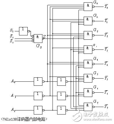
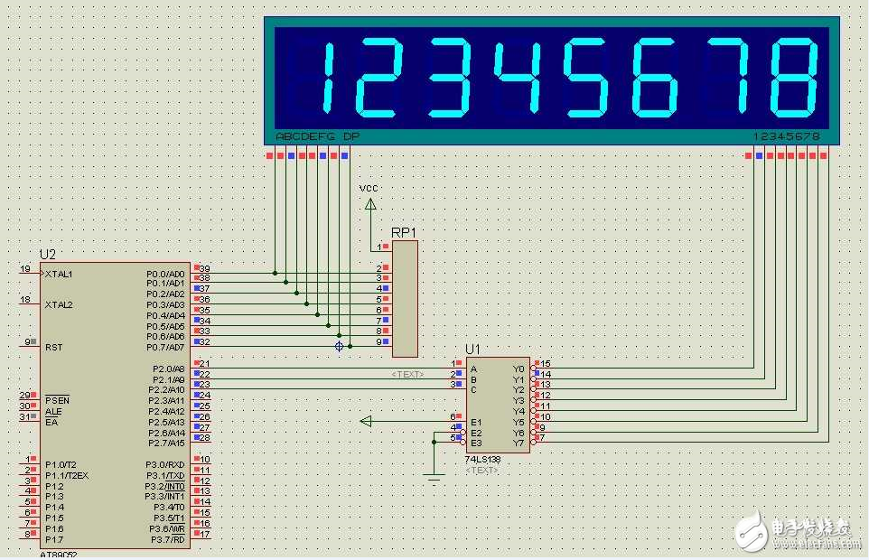
The schematic diagram of the 74ls138 drive digital tube display is as follows: 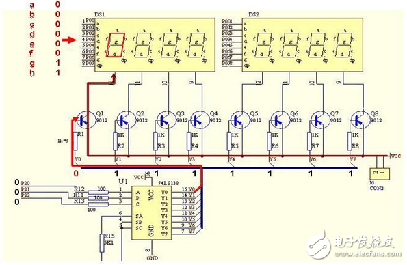
74ls138 drive 8-bit digital tube all circuits and programs share free download:>>>> 74ls138 drive 8-digit digital tube
The 74ls138 drive digital tube circuit diagram is as follows:
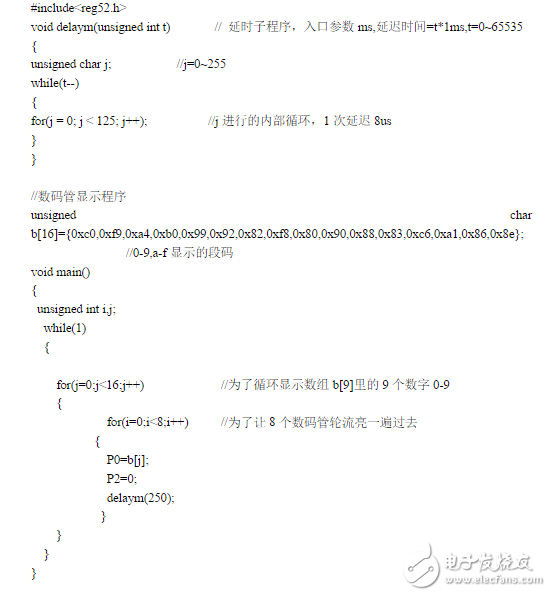
74ls138 drive digital tube part of the program: