Master-slave JK flip-flop circuit The figure is based on the JK flip-flop circuit diagram. JK flip-flop adopts NAND circuit structure. Its working principle is: when CP is 0, the trigger is in a steady state; when CP changes from 0 to 1, the flip-flop does not flip, ready to receive input signal; CP The flip-flop is toggled from 1 to 0; the JK flip-flop accepts information before the falling edge of CP, triggers flipping on the falling edge, and the flip-flop is blocked after the falling edge. China leading manufacturers and suppliers of Level 2 Charger,Ev Charging Stations, and we are specialize in Charging Station,Flexible Group Charging Station, etc. Level 2 Charger,Ev Charging Stations,Charging Station,Flexible Group Charging Station Shenzhen Hongjiali New Energy Co., Ltd. , https://www.hjlcharger.com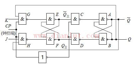
The master-slave JK trigger is based on the master-slave RS trigger. Add an AND gate of two inputs to the R and S terminals of the master-slave RS flip-flop, and output the Q terminal and the input terminal to the original S terminal via the AND gate. The input terminal is called the J terminal, and the Q terminal and the input terminal are The AND gate output is the original R terminal, and the input terminal is called the K terminal.
The master-slave JK flip-flop works from the above circuit to get S=JQ, R=KQ. Substituting the characteristic equation of the master-slave RS trigger:
J=1, when K=0, Qn+1=1;
J=0, when K=1, Qn+1=0;
When J=K=0, Qn+1=Qn;
When J=K=1, Qn+1=-Qn(Qn non);
From the above analysis, the master-slave JK trigger has no constraints. When J=K=1, the flip-flop is flipped once for each clock pulse input. This working state of the flip-flop is called the counting state, and the number of input clock pulses can be calculated by the number of times the flip-flop is flipped.