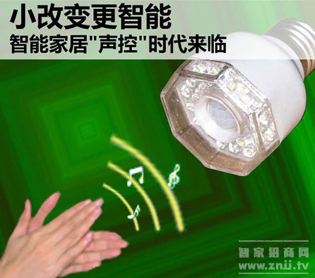
Smart home has entered the “voice-controlled eraâ€. Various voice-activated smart home products emerge in an endless stream. Intelligent voice-activated voice control systems also make people’s lives more convenient. This article is a small series for everyone to introduce intelligent voice control system design. The voice recognition module circuit is designed with reference to the LD3320 data sheet issued by ICRoute. The chip integrates a fast and stable optimization algorithm, eliminating the need for external flash and RAM, which greatly simplifies the design of the circuit. At the same time, the LD3320 does not require the user to pre-train and record in the course of use to complete non-specific human speech recognition, and the recognition accuracy is also high. The LD3320 is directly connected to the STM32 chip in a parallel manner and is pulled up by 1k# resistors. A0 is used to determine the data segment and the address segment. The control signals RDB, WRB, CSB, the reset signal RSTB, and the interrupt return signal INTB are directly connected to the STM32 chip. The LD3320 and STM32 chips use the same external clock (8MHz). The LEDs D1 and D2 are all used for power-on instructions after reset. The MBS pin is connected to an RC circuit as the MIC bias to ensure that a floating voltage can be output to the MIC. . After the voice information is input through the MIC, spectrum analysis is first performed to extract the voice feature information of the voice; then the voice recognizer compares and matches the data in the keyword list with the collected voice feature information to find the keyword with the highest score. Speech recognition result output. The wireless sensor network communication protocol adopts 820.15.4E, and the wireless SOC chip of model CC2430 is selected. The chip has abundant on-chip resources, and the necessary circuits have been integrated in the chip. Only a relatively simple peripheral circuit is needed to use, and data can be wirelessly transmitted and received. Y1 is a 32.768kHz crystal oscillator, which is combined with two capacitors (C1, C2) to form a 32.768kHz crystal oscillator circuit; Y2 is a 32MHz crystal oscillator, which is combined with two capacitors (C3, C4) to form a 32MHz crystal oscillator circuit; capacitor C5 and inductor L1 , L2, L3, and a PCB microwave transmission line combine to form an unbalanced transformer circuit of the WSN circuit. The peripheral voltage is configured with a filter capacitor to ensure the stability of the chip operation. The entire circuit design meets the RF input/output matching resistor (50Ω) specification. In addition, a filter capacitor is added to the voltage pin and ground pin to provide stability for the chip. Because embedded mobile terminals need to be portable, wireless, and have low power consumption, a large-capacity, high-performance lithium battery is used in the power management section. The power management circuit mainly includes three parts: a lithium battery charging circuit, a lithium battery protection circuit, and a voltage conversion circuit. Among them, the lithium battery charging circuit is mainly implemented using the MAX1555 chip and the corresponding resistors and capacitors. Lithium battery protection circuit consists of FS8820P battery protection chip, resistors, capacitors. Since the working voltage of the chip used in the terminal hardware circuit is 3.3V and the input voltage of the lithium battery is 0 4.2 4.2V, the voltage conversion using the MAX8881 is required. The hardware circuit of the entire embedded portable voice controller mainly includes four parts: MCU circuit, voice recognition circuit, WSN circuit and power management circuit. Since the embedded portable voice control terminal must be portable, miniaturized, and low power consumption, this requires the MCU chip to have higher integration and low power consumption, and facilitate the low-power function setting. Therefore, the chip used by the MCU is the STM32F103RX based on the Cortex-M3 architecture. The STM32F103RX chip acts as a 32-bit standard Reduced Instruction Set (RISC) processor and performs the high performance of the ARM core on the storage space of typical 8- and 16-bit systems; it integrates Flash memory, SRAM, and rich I/O interfaces. Advanced interrupt response systems are more suitable for use in this scenario. The voice control chip used in this solution is LD3320 of ICRoute. The chip used for WSN communication is CC2430. The terminal initiates activation via a button. After receiving the external voice information, the MIC first analyzes the information through the voice recognition module to obtain the required data; then the data is sent to the MCU through the serial port, and the MCU analyzes the corresponding device actions after processing. Command; After the serial port will send information to the CC2430, and finally to the home gateway, thus enabling wireless voice control of the smart home interior controllable appliances. Article : How to represent smart home? ã€Intent to join agents must read】 Recommended : smart home model room smart home laboratory smart home initial fee Brake Disc For KIA Kia Brake Disc,Kia Auto Brake Disc,Kia Car Brake Disc,Kia Automobile Brake Disc Zhoushan Shenying Filter Manufacture Co., Ltd. , https://www.renkenfilter.com Speech Recognition Module Design

WSN communication circuit design
Power Management Circuit Design

hardware design
Related browsing