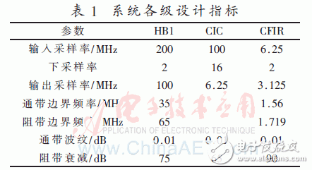
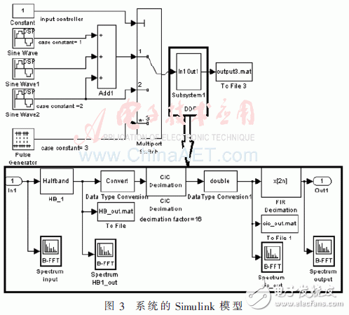
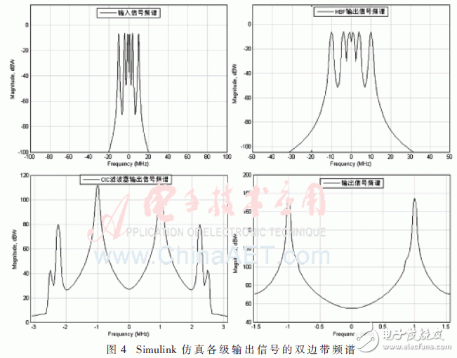
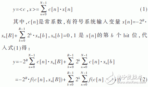
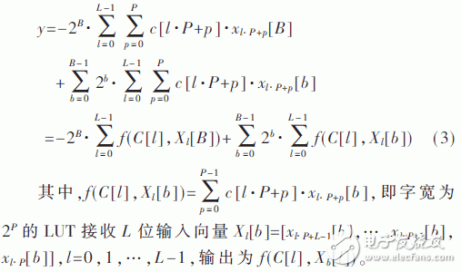
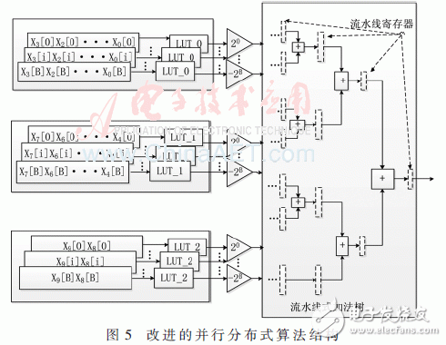
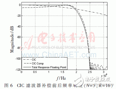
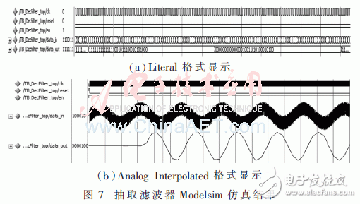
Abstract: Aiming at the downsampling requirements of digital down-conversion high-speed digital signals in software radio receivers, a half-band filter pre-stage multi-stage decimation filter architecture is designed by using half-band filter and cascaded integrative comb filter. . After simulating the system model verification with Simulink, a decimation filter with a downsampling ratio of 64 was implemented on the Xilinx xc5vsx95t-2ff1136 FPGA using Xilinx ISE 12.3. The simulation results of Modelsim show that the decimation filter design is effective and meets the design specifications. Digital down conversion is a key module of software radio receiver. High-speed digital signal is used for frequency conversion, downsampling and filtering, and the high-speed intermediate frequency signal is changed into low-speed baseband signal [1-2], which is convenient for post-processing. Among them, downsampling and filtering are the key modules of downconversion, which are done by decimation filter [3]. Since the multi-stage structure can greatly reduce the order of the filter [4], allowing the normalized transition bandwidth of each stage to be wider [5], the decimation filter is generally implemented in a multi-level structure, and the common structure is shown in Figure 1, wdz4 The -t1.gif Cascaded integrator-com (CIC) filter is usually used as the first-stage decimation filter [1-6]. In order to shorten the critical path and thus increase the sampling speed, the filter often uses parallel processing and pipeline technology [6]. There is a feedback loop in the CIC filter. Adding to the pipeline register will cause the feedback loop to be out of sync, which makes it impossible to use pipeline technology. The FIR filter can use parallel processing and pipeline technology. For the Half-band Filter (HBF), the distributed algorithm is well compatible with parallel processing and pipeline technology, and does not require rate-limited multiplier resources. This design improves the pipelined full parallel distributed algorithm to achieve HBF, while parallel processing increases the sampling rate by using the method of copying hardware [7], wdz4-t2.gif full parallel structure of HBF is copying using LUT, To meet the processing speed requirements, this paper places the HBF at the input level with the smallest data bit width (Figure 2). In this paper, the total decimation rate of 64-times decimation is divided into three levels: the pre-extracted HBF with 2 times extraction, the CIC decimation filter with 16 times extraction, and the FIR compensation filter with 2 times decimation, as shown in Figure 2. The indicators at various levels are shown in Table 1. Simulink is a visual simulation tool in MATLAB that can simulate and analyze dynamic systems, support multi-rate systems, and is widely used in modeling and simulation in the field of digital signal processing. The system model of this paper is shown in Figure 3. The top-level system uses three signal selectors as input interfaces, and the input signals are downsampled and filtered via a subsystem shown in the rectangular box, ie, a decimation filter. The coefficients of the FIR compensation filter are obtained in Section 2.3 of this paper. Set the input control signal to "1", select the mixed sinusoidal signal with the sampling rate of 200 MHz at 1 MHz, 4 MHz, and 10 MHz as the input signal of the decimation filter. The spectrum of the output signals of each level is shown in Figure 4. . 2.1 Pre-semi-band filter HBF is nearly half of the FIR filter with a coefficient of 0. The use of HBF in multi-rate systems can greatly reduce the hardware scale. This paper combines the advantages of table segmentation technology and parallel processing to improve the first-level high-speed processing. Consider the inner product formula: Consider N=LP, L and P are positive integers, then n=l·P+p, l=0,1,...,L-1,p=0,1,...,P-1, (2) Rewritten as: In this paper, the 35-step high-speed HBF coefficient is symmetrical, and nearly half of the coefficients are zero. Select P=4 to decompose the entire LUT table into two 4-input and one 2-input sub-tables. The improved algorithm structure is shown in Figure 5. Compared with the literature [8], the pipelined addition tree after look-up table has higher real-time performance than the shift accumulator; parallel and pipeline processing can effectively improve the processing of the filter. Speed, and table partitioning techniques make this parallel structure not necessarily at the expense of excessive resource consumption. 2.2 CIC decimation filter The CIC filter is simple in structure and is a very efficient unit in high-speed extraction or interpolation systems [9]. The first sidelobe suppression of the single-stage CIC filter is 13.46 dB, and the stopband attenuation is extremely unsatisfactory [10]. In order to achieve the index of the stopband attenuation, this paper uses a multi-stage CIC filter cascade structure. The normalized transfer function of the N-level CIC filter is as follows [11]: Where R is the decimation factor and M is the amount of delay in the comb portion. This design takes M to be 1. The amplitude-frequency response of the CIC extracted by the N-order R-times from equation (4): It can be calculated that the requirement of the stop band attenuation can be satisfied when R=5. This article first implements all the integrators, then 16 times the extraction, and finally the comb portion. For multi-stage CIC filters, some of the less significant bits can be clipped without affecting the integrity of the system [7]. This paper adopts a step-by-step clipping method to reduce the quantization noise caused by bit width truncation and save resource occupation. In this design, the CIC filter input bit is 19 bits wide, the output is 20 bits, and the internal maximum bit width is 40 bits. After stepping off, the width of the CIC filter is shown in Table 2. The CIC filter frequency response is shown in Figure 6. It can be seen that the passband attenuation is one of the main drawbacks of the CIC filter, so the compensation filter is required for passband compensation. 2.3 CIC compensation filter The compensation filter is typically at a lower rate to reduce hardware complexity. To avoid spectral aliasing, the passband boundary frequency fc of the compensation filter of this paper should satisfy: fc≤fs_cic/4R, and fs_cic is the input sampling frequency of the CIC filter. In this paper, the compensation filter selects fc=1.56 MHz. Because its frequency response is the reciprocal of the CIC filter frequency response [12], namely: Based on equation (6), the floating point coefficient is calculated using the firceqrip function in MATLAB, and then quantized. After repeated trials, the compensation filter length is 33. At this time, the compensated filter passband ripple is less than 0.01 dB, and the compensation filter and the compensated filter frequency response are as shown in Fig. 6. It can be seen that the compensation filter design is more reasonable. Since the output bit width of the CIC filter is 20 bit wide and the bit width is large, the filter does not use the structure shown in FIG. 3, and the IP core is used to introduce the filter coefficient, and the pulsation array multiply-accumulate structure is selected. Use MATLAB to generate mixed sinusoidal signal data with a sampling rate of 200 MHz and frequency of 1 MHz and 18 MHz, and write the data into the TXT file. Then read the data into the FPGA register and simulate the output of the ADC as the input of the system under clock excitation. . The simulation results of Modelsim are shown in Figure 7. It can be seen from Fig. 7(a) that there is one output every 63 input data, which achieves the purpose of 64 times extraction; and Fig. 7(b) shows that the waveform is smoother, and the error caused by the bit width truncation is basically negligible, indicating that this paper The bit width phase mode of the stepwise pruning is effective. In this paper, a kind of HBC pre-decimation filter structure is designed for the requirement of down-sampling rate in digital down-conversion. The system was modeled and simulated by Simulink, and the design method of the FPGA to realize the various stages of the filter was explained in detail. The Modelsim simulation of the whole system was carried out. The results show that the decimation filter designed in this paper has good performance and fully meets the actual demand index. And the design of this paper has strong engineering application value, and has been used in the digital down conversion system with medium frequency 200 MHz. We provide quick-turn injection molding by many types of materials, like ABS, PA66, PBT, TPU, TPE, PVC, PE, NYLON 6, PC, silicone, TPE, EPDM, PUR, etc. Special for some plastic parts. Our advantages in internal prototyping, bridge tooling and short-run manufacturing, which can eliminate the costly and time-consuming for customers a lot.
ETOP experienced to support one-stop cable assembly solution service, including wire harness, palstic enclosure, silicone, metal, PCBA, etc.
Injection Molding Parts,Plastic Injection Molding,Low Cost Plastic Injection Molding,Plastic Mold Injection Molding ETOP WIREHARNESS LIMITED , https://www.wireharness-assembling.com