First, the pipeline wiring The pipeline wiring is pre-buried in the floor when pouring concrete. The steel wire or iron wire of the traction cable is used in the pipeline. The construction plan can be made only by understanding the floor pipe through the pipeline drawing during construction. For new buildings without pre-buried pipes, the wiring construction can be synchronized with the building decoration, which is convenient for wiring without affecting the aesthetics of the building. The pipe is generally buried from the wiring closet to the information socket mounting hole. When the twisted pair wire is fixed at the terminal of the information socket during construction, the cable can be led to the wiring closet by pulling the cable from the other end of the pipe. Second, the ceiling wiring 1. Request construction drawings and determine routing routes; 2. Along the designed route (ie in the cable tray body), open the ceiling and push each panel with both hands; 3. Discharge multiple cable boxes together and make the outlets upward; 4. Add the mark, the mark can be directly written on the carton, the mark of the cable is written at the end of the cable, and the label is attached; 5. Connect a suitable length of traction wire to a coil; 6. Starting from the farthest end from the wiring closet, pull the ends of the cables (bundled together) along the cable tray through the end of the ceiling corridor; 7. Move the ladder to pull the cable to the next hole in the ceiling until the rope reaches the end of the corridor; 8. Pull out the cables in each of the 2 boxes to form a "pair" and bundle them with tape; 9. Pass the drawstring through three pairs of cables wrapped with tape, form a loop, and tie the three pairs of cables to the rope with a strap; 10. Return to the other end of the drawstring and manually pull the drawstring. All 6 cables (3 pairs) will be automatically pulled out of the line box and pulled through the cable tray to the wiring closet; 11. Repeat step 8 for the next set of cables (additional 3 pairs); 12. Continue to add the remaining cable sets to the drawstring, pulling them forward each time until the end of the corridor, and then continue to pull the cables until they reach the wiring closet. When the cable is finished in the ceiling, the cable should be led down to the information socket mounting hole through the wall or wall post pipe. Wind the twisted pair into a tight group and feed the end into a PVC round tube embedded in the wall and press it down until it is exposed to 25-30 mm at the socket hole.
24HR Electronic Timer socket with photocell.
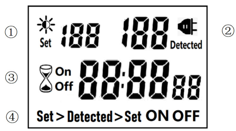
â‘ Light intensity setting
â‘¡ Light intensity detection
â‘¢ Countdown Timer ON & OFF
â‘£ 4 MODES:
Set > Detected: When the light intensity detection value is less than the set value, switch ON or OFF.
Detected > Set: When the light intensity detection value is greater than the set value, switch ON or OFF
ON : Always ON
OFF : Always OFF
NOTED:
1. The light intensity displayed by this machine is not the standard light intensity value (Lux), only the relative light intensity value.
2. The light intensity value is affected by the placement position and direction. Please determine the position first and then set it according to the actual light intensity detected. If you change the position or change the orientation, you need to reset the light intensity setting value suitable for the new position.
3. This product has built-in rechargeable battery. If it is not connected to AC for a long time, you need to connect the power supply to charge until the LCD can display normally.
MANUAL OPERATION
1. Press [UP" or [DOWN" to set the LUX value.
2. Press the [SET" key to start setting, and the P1 settable items will be flashed.
3. Press [UP" or [DOWN" to adjust the value.
4. Press [SET" key again to exit setting or enter next setting for countdown timer.
5. Repeat the [SET" key to start setting, and the P2 & P3 settable items will be flashed.
6. Press the [FUN" key to switch the working state in the following:
Set > Detected -> Detected > Set -> ON -> OFF
Set > Detected: Automatically switches when the detected ambient light intensity is darker than the set value
Detected >Set: Automatically switch when the detected ambient light intensity is brighter than the set value
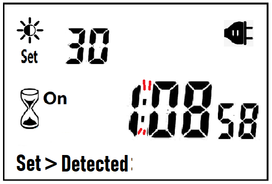
When the brightness meets the setting conditions, the countdown starts as below:
Note:when the countdown is ON, the detected value is not displayed.
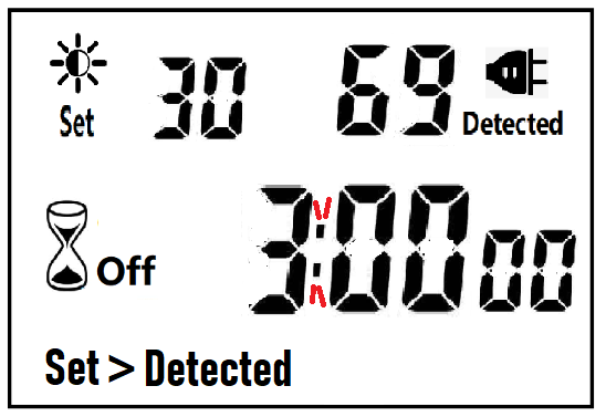
When the brightness does not meet the setting conditions, the countdown stops and waits:
After the countdown ON is reduced to 0, the countdown OFF starts immediately and the power is OFF.
A. If the light intensity meets the set conditions, a new round of countdown will be started;
NOTE:
1. If the power is cut off while the countdown is running, the countdown will be terminated immediately and the relay output will be off. After the power is turned on again, a new round of brightness detection will start.
2. Modifying the brightness value in the countdown operation will not affect the current countdown operation. After the off time of the current countdown, the new brightness setting value will take effect.
3. In the countdown on operation, change the setting value of the countdown on, this countdown will still be timed according to the original setting value; the new setting value will take effect when the next countdown on starts.
Manual Control
Power Detection and Standby Mode
Photocell Timer, photocell timer socket, photocell sensor, photocell sensor socket, sensor plug, sensor switch socket, digital photocell timer, digital sensor timer NINGBO COWELL ELECTRONICS & TECHNOLOGY CO., LTD , https://www.cowellsocket.com


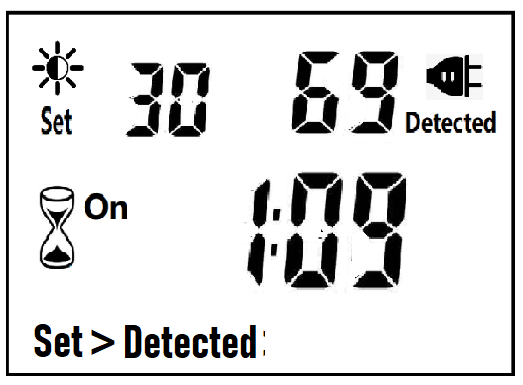
After the countdown OFF is reduced to 0:
B. If the light intensity does not meet the set conditions, keep the power off and wait for the light to meet the conditions before turning on automatically.
4. In the countdown off operation, change the setting value of countdown off, this countdown will still be timed according to the original setting value; the new setting value will take effect when the next countdown off is started.
NOTE: the brightness setting value, countdown ON or countdown OFF, any one of which is equal to 0, cannot be switched ON or OFF automatically.
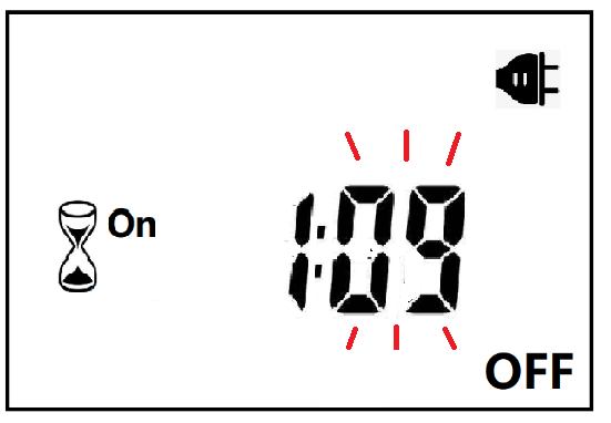
When ON or OFF is displayed, it means that the power supply remains ON or OFF, as shown in the figure below:

With AC power supply, the icon ![]() lights up and works normally.
lights up and works normally.
When there is no AC power supply, the icon ![]() goes out, the brightness is not detected at this time, and the system enters the standby mode.
goes out, the brightness is not detected at this time, and the system enters the standby mode.