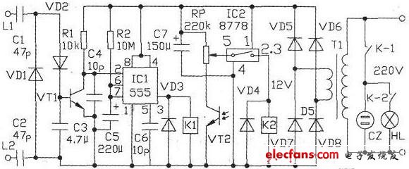
1. Circuit working principle The circuit is shown below. When the phone is on-hook, there is a voltage of 45-60V between the telephone lines L1 and L2. Due to the action of the capacitors C1 and C2, the delay circuit composed of components such as the integrated circuit IC1 cannot be triggered. When the call comes in, the ringing signal from L1 and L2 is in an alternating state. The capacitors C1 and C2 are coupled, the diodes VD1 and VD2 are double-voltage rectified, and the capacitor C3 is filtered to form a forward DC voltage applied to the base of the triode VT1. Extremely, the VT1 is saturated and turned on. At this time, the (2) pin of IC1 changes from a high level to a low level, and the output of the (3) pin of IC1 changes from a low level to a high level, so that the relay K1 is pulled. The normally open contact K1 is turned on, and the radio or tape recorder inserted in the power socket CZ can play the radio broadcast program or the tape content. If the phototransistor VT2 is high impedance when it is dark, the relay K2 is attracted by the action of the integrated circuit IC2, and its normally open contact K2 is also turned on, and the electric lamp HL is illuminated. After IC1 is triggered, the power supply charges capacitor C5 through resistor R2. When the voltage across C5 rises to 2/3 power supply, IC1 is reset, and its output (3) pin goes low again, radio or recorder and lamp. Open and close at the same time. When the call is re-entered, the process will be repeated over and over again. 2. Selection of electronic components IC1 can use the time base integrated circuit of NE555 and LM555. IC2 selects TWH8778 integrated circuit produced by Dahua Electronics Factory of Guangdong Province. VT1 uses 9013, 8050 NPN type triode. VT2 uses a 3DU31-33 type phototransistor. VD1, VD2 select 1N4001 type diode, VD3, VD4 use 1N4004 type diode, VD5, VD6, VD7, VD8 use 1N4007 type diode. The relays Kl and K2 are all of the JRX-13F type, and the coil operating voltage is 9V. T1 uses 8W, 220V/9V power transformers. There are no special requirements for other RC components, which can be selected according to the parameters listed in the figure. 3. Installation and commissioning After the circuit is installed correctly, it can be commissioned. First replace the resistor R2 with a 100kΩ resistor, and integrate L1 and L2 into the telephone line to let others dial your call. At this time, the relay K1 should be sucked in, and K1 is released again after about 30s. Then adjust the resistance of the adjustable resistor RP so that the relay K2 is in the released state when there is light to VT2, and K2 is closed when the light is weak. Finally, replace R2 with a 10MΩ resistor. Changing the value of resistor R2 and capacitor C5 can change the delay time. When installing the phototransistor VT2, avoid direct illumination of the light to prevent interference. When using, plug the power plug of the tape recorder into the power socket CZ, turn on the power switch, adjust the volume, and tune to a station with a late broadcast. Or plug the power plug of the tape recorder into the power socket CZ, put a 60-minute tape, press the play button, and adjust the volume. Wireless Charger Car Phone Holder Wireless Charger Car Phone Holder,In Car Phone Holder Wireless Charger,Car Phone Holder And Charger,Phone Car Mount With Wireless Charger Ningbo Luke Automotive Supplies Ltd. , https://www.nbluke.com