Description of Right Angle D-SUB Connector
The right angle d-sub is an ideal connector solution for applications where space is at a premium and there is little to no room for connectivity & cabling. The 90° angle cable exit allows for increased mounting options and versatility of design for those tighter, more compact application needs such as computer servers and industrial robotics.
Antenk RIight's Angle Standard D-SUB Connector Series Including:
Standard D-Sub Right Angle Machined
Standard D-Sub Right Angle Stamped
Antenk RIight Angle High Density D-SUB Connector Series Including:
High Density D-Sub Right Angle Stamped
Antenk's RIight Angle D-SUB Connector Options
Number of Rows
Shell Size
Mounting Style
Packaging
Gender
Shell
TARGET MARKET / APPLICATION
Communications
Base Stations
Switching
Transmission
Asymmetric Digital Subscriber Line (ADSL)
Data
Desktops/ Laptops
UPS, Storage systems
Routers, Servers
Printers, Copiers
Consumers
Consumer Electronics
Set-top-boxes
Energy meters
Industrial & Instrumentation
Robotics
Control Drives
Power Supplies
Medical Instruments
Test Equipments
POS & Handheld terminals
Renewable Energy
Surveillance Camera
Office Automation
Parking Meters
Gaming Machines
Military
Military
Avionics
Military Equipment
Standard Density right angle D Sub Connector machined contacts, Right Angle High Density D-SUB Connector,Standard Density right angle D Sub Connector stamped contacts ShenZhen Antenk Electronics Co,Ltd , https://www.antenkelec.com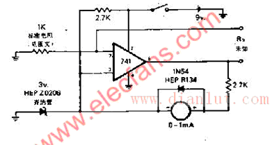
Ohm table circuit diagram
Standard & HD D-Subs SMT Right Angle & RA Zero Footprint Through Hole
VGA over Dual PS/2 ports Stamped Contacts
High Density D-Sub Right Angle Machined
Dual-Port D-Sub
Standard & HD D-Subs SMT Right Angle & RA Zero Footprint Through Hole
High Density D-Sub Right Angle Stamped
The circuit has a linear reading scale, does not need to be calibrated, and does not need to be zeroed. By switching different standard resistors through the switch, it can be made into an ohmmeter with a K range (the ohmmeter is a meter for measuring resistance, and the diagram is a measurement schematic of an ohmmeter). G is an ammeter with an internal resistance of Rg and a full-scale current of Ig, R is a variable resistor, also called a zero-resistance; the battery is a dry battery, the electromotive force is E, the internal resistance is r, and the red test pen (insert "+" The jack is connected to the negative pole of the battery; the black test lead (inserted into the “-†jack) is connected to the positive pole of the battery. When the measured resistance Rxr is small compared to Rg and R, it can be ignored.