VR1 is the left and right channel balance potentiometer (VR1a represents one channel). The B-type potentiometer with ALPS 100kΩ×2 with intermediate positioning is used. I use the old gold foot ECC88 for the input tube G1, the 6DJ8, 6N11 and 6N2 for the output tube G2. Different tubes have different sounds. The higher the internal resistance, the stronger the biliary taste. I love to use 6DJ8 to listen to the blow. Le, listen to silk music with 6N11, and listen to love songs with 6N2. In fact, the circuit is very adaptable, and even with 6N1, it has a very good sound. Since the pins of the above tubes are the same, they can be interchanged, and different tubes have different optimal working points, but the adaptability of the tubes is very strong, and the screen pressure can work from 60V to 500V. When the screen pressure is constant, the smaller the negative grid voltage, the larger the screen flow, the lower the frequency and the impulse are better, but the noise is relatively larger. However, the negative gate voltage should not be too large. If the screen current is too small, the cutoff distortion is likely to occur. This is because the SRPP circuit is a parallel adjustment push-pull circuit, and the tube works better in Class A. Communication Backup Lithium Battery System 48V Dc Battery System,Lithium Battery System,Long Cycle Time Battery System,Communication Backup Battery System Wolong Electric Group Zhejiang Dengta Power Source Co.,Ltd , https://www.wldtbattery.com
In order to take care of the signal-to-noise ratio and use various tubes more conveniently, when G1 and G2 use 6DJ8, the cathode resistances R3 and R4, I use 1.2k and 1.5k respectively, and the negative gate voltage is about -2.2V. The trade-off for R1 depends on the person. If the output level of the laser player is not high, it can be discarded. C1 and C5 are best made of polypropylene capacitors, and no mica capacitors are used, but the accuracy is accurate. Cross-connect capacitors C2, C3, and C4 may only use Wima's MKS, because the position left by this board is limited. Of course, if the potentiometer's sleeve is not touched, C2, C3, and C4 can be erected. High and low potentiometers VR3, VR2 I use a 1MΩ potentiometer made in Taiwan. The spacing between the two rows of feet is very wide. If there is no potential of 1MΩ, at least 500kΩ should be used. Otherwise, the improvement of high and low sounds should be Affected.
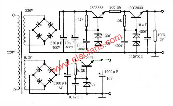
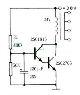
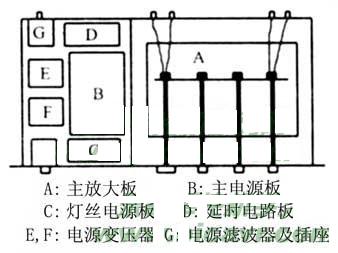
For each channel - only 50W E-type old transformer. High-voltage power supply adjustment tube is the best switch tube, as long as the withstand voltage is greater than 400V, the power is greater than 15W, here I use the disassembled switch tube 2SC3833. High-voltage delay circuit board (Figure 1) I am from other expenses The power amplifier board is made of sawing one piece. The relay uses 24V, and the delay time is about 9 seconds, which is determined by the product of R1 and CT. If you replace R1 with a 2M resistor, the delay time is about 9 minutes. Due to the different transistors, the pin arrangement is not the same, and the high and low voltage power supply is also relatively simple, so I did not attach the power board and the delay board circuit board diagram. Figure 2 is a diagram showing the position of each part of the whole machine. Figure 3 is a layout of the printing plate and components.
The AC power filter uses a small product with a TDK1.5A and 250V socket. The rods of several potentiometers are made of aluminum rods with a diameter of 10 mm.
The chassis is made by itself, with a width of 430mm, a depth of 280mm, a height of 80mm, and a panel length of 480mm. The balance and the pitch of the high and low potentiometers are 4.5cm.