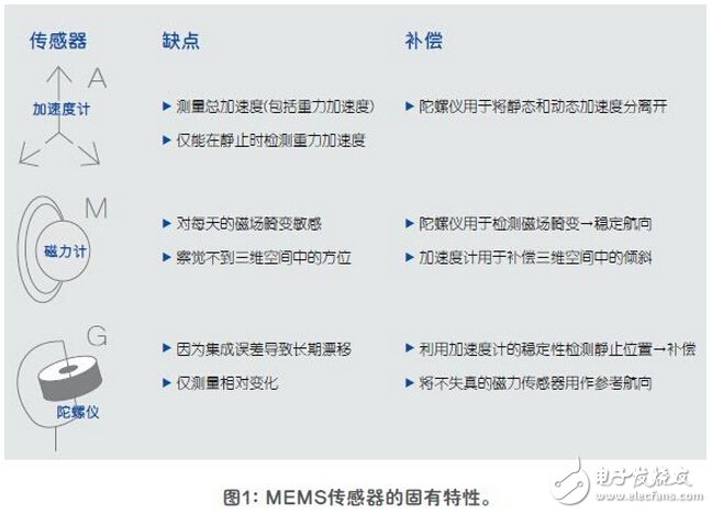
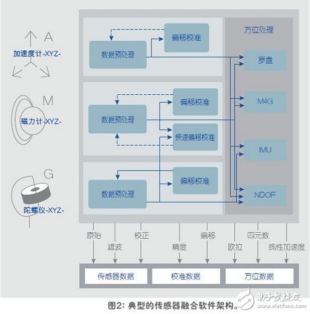
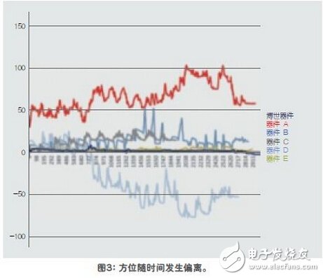
With the continuous advancement of powerful smart devices such as smart phones, new applications are emerging, and system development often fails to keep up with changing new requirements. Today, new applications that use motion or location data, such as indoor navigation and augmented reality, require users to accept less-than-perfect sensor fusions that were originally developed for simple gaming applications. However, it is easy for end users to discover that these implementations have considerable drawbacks and are very low precision. Sensor Fusion is an innovative engineering technology that combines data from a variety of system sensors to ensure more accurate, complete and reliable sensor signals or sensory information. To achieve consistent sensor fusion, it is important for engineers to understand the strengths and weaknesses of sensors before deciding how to optimize the integration of data from these sensors. One method that can be successfully implemented is to use a fusion database of sensor signals based on accelerometers, magnetometers, and gyroscopes, and to provide high-precision, reliable, and stable orientation data by compensating for the shortcomings of each sensor. As end users continue to reach out to these new applications, they hope to have more accurate and reliable solutions. The use of sensors to track the user's indoor navigation between known fixed locations is very similar to earlier GPS devices, and only the combination of superior quality sensors can provide the required fidelity, accuracy and even user confidence. OEMs understand this, so most vendors believe this is a good opportunity to achieve product differentiation. Another example is the advancement from virtual reality to augmented reality. In virtual reality (VR) systems, users are isolated from the real world and immersed in an artificial world. In an augmented reality (AR) system, users can still interact with the real world while interacting with virtual objects around them. With existing technology, the delay in information transfer is unbearable to the user - this misalignment in augmented reality can lead to a very poor user experience. For OEMs and platform developers (ie operating system developers), the biggest challenge is to ensure that all devices provide the performance to meet the stable operating requirements of these applications. For example, there are many different combinations of hardware and software in an Android device, each of which produces a different output quality. There are currently no standard test procedures, which means that application developers cannot rely on Android sensor data to achieve the same performance on many different platforms. The following are recommendations for analyzing and comparing the performance of different hardware and software combinations to set minimum performance standards using a motion tracking camera system. Performance analysis is achieved by measuring the system's four key performance indicators (KPIs): static accuracy, dynamic accuracy, azimuth stabilization time, and calibration time. The camera system generates orientation vectors based on the motion of the object (smartphone) by tracking the markers on the object, which are then compared to the vectors created by the sensors in the handset. The data logging application simultaneously records these vectors, which support direct comparison of end user devices. This article introduces the concept of sensor fusion in a smartphone environment, discusses how to use sensor fusion software to improve overall accuracy, and introduces a test method that includes performance measurement measurements performed on many flagship smartphones. The fusion library described in this article uses accelerometers, magnetometers, and gyro sensor signals to compensate for each other's shortcomings and to provide highly accurate, reliable, and stable orientation data. The following sections focus on the pros and cons of these key devices and how they compensate for each other's shortcomings. The orientation of the object describes how it is placed in three dimensions. In general, the orientation is defined relative to the reference frame specified in a coordinate system. At least 3 independent values ​​are required as part of the 3D vector to describe the true orientation. All points of an object change their position during rotation, except for points on the axis of rotation. Magnetometer Magnetometers are highly sensitive to disturbing local magnetic fields and distortions, which can easily cause errors in the calculated magnetic heading. Gyroscopes can be used to detect such disturbances and heading changes without rotation recording. Sensor fusion can then be accurately compensated by providing the gyroscope data with more weight than the magnetometer data. The horizontal component of the Earth's magnetic field is used to calculate the magnetic heading, while the pitch and roll angles are the tilt angles along the horizontal (X) and vertical (Y) axes, respectively. These tilt angles affect the magnetic field in the XY axis direction. When the device is not in the horizontal position, ie the tilt angle is not zero, the heading calculation will be incorrect. Therefore, it is important to ensure that these tilt angles are compensated before using the accelerometer to calculate the azimuth by rotating the XY plane. Accelerometer The accelerometer can only measure the total acceleration value due to the acceleration caused by the motion of the device and the acceleration caused by the gravity, and cannot detect the difference between the two, so it is necessary to separate the gravity from the motion: Linear acceleration = acceleration - gravity acceleration The gravity vector can be thought of as a three-dimensional vector that indicates the direction and magnitude of gravity. When the device is at rest, the output of the gravity sensor should be the same as the output of the accelerometer. The linear acceleration can be thought of as a three-dimensional vector indicating the axial acceleration of each device and is considered independent of the gravity component in mobile applications. At this point, the gyroscope is used. The gyroscope can be used to detect when the device is at rest and trigger the calculation of the gravity vector offset calibration. The result can be used to calculate the dynamic component (linear acceleration) during motion of the device. Gyro The gyroscope can provide a rotational speed around the three axes and can therefore be used to track the position of the device during motion. Gyroscopes can track rotation speeds of up to 2000 degrees per second (dps), while magnetometers can track speeds below about 400dps. However, the gyroscope can only output relative positions, so a magnetic sensor that is not distorted is required as a reference. All consumer-grade gyroscopes have inherent drift errors, so even if the device is in a steady state, the gyroscope will rotate to some degree with time and temperature. In order to correct these errors, the static state can be detected with a highly stable accelerometer and then compensated appropriately by calculation. Real world design Sensor fusion is a highly specialized design area that requires proficiency in modeling and simulation techniques. It requires the best possible understanding of the sensor's working details and their shortcomings and interactions. Over the years, people's concerns have been brought into the fields of navigation, smartphone apps and games. But until now, with the accumulation and accumulation of a large amount of knowledge, people can get real and accurate results. In sensor-based fusion systems, operations require fine tuning. Nothing in the real world is as simple as "plug and play." The commissioning of a system requires that parameters be adjusted and that there is interaction between the operations of each sensor, so it can easily become a highly complex iterative process. Today's software has the ability to perform this "fine tuning" at a high level and provides OEMs with simple and intuitive filter adjustment procedures. Pre-defined filters make fine adjustment faster Since fine-tuning of sensor fusion operations has evolved and simplified into filter tuning tasks, it provides developers with a valuable opportunity. By properly adjusting the filter, developers or OEMs can make the final product run in a market-differentiated manner. Because the balance of ownership management is automated, developers can make effective decisions, such as balancing trade-offs between highest stability and maximum performance to fit the final target market. Key performance indicator measurement settings All sensor fusion techniques are not identical. There are significant differences between different vendors in terms of existing implementation techniques and testing. In order to get the right results, the correct software method with a proven, accurate library must be used. All hardware must be compatible and matched in terms of interface and timing parameters. A reasonable approach is to ensure the performance of the camera system, which will generate a position vector by moving the marker on the object according to the object (in this case, the smartphone). The orientation vector is then compared to the vector created by the sensor and recorded simultaneously with the data logging application. Using this camera-based system allows direct comparison of the final commercial device. Static accuracy Static accuracy is defined as the deviation between the measured device orientation and the actual device orientation when the device is placed in a stable position. In order to calculate the static accuracy, the mobile phone needs to collect the set data of heading, pitch and roll when it is placed at multiple positions. The static accuracy of a device is primarily influenced by the hardware parameters of the magnetometer and gyroscope and the weights assigned to them in the software. In devices with low static accuracy values, the end user can see large deviations in the absolute heading of the compass or map application, and when the device is in a static state, they can also see jitter in the interactive application (small rotation) mobile). This is due to software correction of gyroscope drift. Dynamic accuracy Dynamic accuracy is defined as the deviation between the measured device orientation and the actual device orientation when the device is in motion. It is more difficult to measure because of the rotational acceleration involved during the movement. Dynamic accuracy is calculated by collecting sets of data such as heading, pitch and roll when the phone is moving in different modes of motion (8-word dance, slow linear, fast and slow rotation, and game action). All data is collected at the fastest possible data rate. In devices with low dynamic accuracy, the end user can see a large deviation between the movement on the screen and the actual motion of the device. This is particularly noticeable in augmented reality applications because the movement of the enhancement unit is not synchronized with the real world. This is one of the reasons why users are dissatisfied after using virtual reality for a few minutes. Although the direct relationship is not obvious, the dynamic accuracy of large errors is also the main reason for the poor performance of indoor navigation applications. Since the user navigates between known fixed points (such as starting with a Wi-Fi or Bluetooth beacon), the sensor data can be used to calculate the trajectory. However, heading errors will accumulate over time, so devices with 15° poor dynamic accuracy can easily produce cumulative errors of more than 100° in 20s to 30s. Higher layer processing such as map matching may be able to make some corrections, but at the cost of greater power consumption. Calibration time Calibration time is defined as the time required to calibrate a magnetic sensor in a pure magnetic field environment from an uncalibrated state to a fully calibrated state. All magnetic sensors require calibration, but the method used for calibration defines whether the end user needs calibration and how to calibrate. Some devices use a 8-word dance calibration method that prompts the end user to calibrate the device by performing an 8-word motion in the air. Even with experienced testers, this method takes 5s to 6s to complete the device calibration. A device with a shorter calibration time uses a gyroscope to calibrate the magnetic sensor, which means that the calibration can be run in the background and the required device movement is much smaller. These movements are usually performed during normal operation, and the end user never has to actively calibrate the sensor. Bosch Sensor Technologies' Fast Magnetic Calibration (FMC) algorithm uses the latter method to ensure shorter calibration times. Azimuth stabilization time Azimuth stabilization time is defined as the time required to reach a precise, stable azimuth state after "after exercise." The azimuth stabilization time should be as short as possible so that the user does not see the delay between stopping the mobile device and stopping the device from moving to the correct position. This delay on the device is significant when the static and dynamic accuracy of the device is poor, as more time is required to correct for errors accumulated during the move. This effect is especially annoying in games and virtual/augmented reality applications that require real-time response. From a detailed assessment and analysis, it is clear that the sensor fusion described in this paper can now be widely used in professional and consumer markets. Field trials have shown that users can get valuable upgrades in performance and accuracy. While hardware and software concepts and engineering are complex, the task of transitioning from current sensor fusion to this advanced solution is relatively straightforward for developers. Sensor fusion technology has now evolved to a fairly mature stage. By integrating the sensor and sensor fusion building blocks into the same package, you can ensure that these units are optimized and work well together. System designers no longer need to spend time assembling, optimizing, and debugging traditional “always on†subsystems because each device is optimized for the highest accuracy and lowest power. This high level of technology and design creativity gives developers the advantage of providing great benefits to OEMs. Not only can they introduce highly differentiated products to the market, but they will also provide significant new generation of electronic devices to users. Improved performance and efficiency. Bubble Bag Machine,Dense Bag Cutting Machine,T-Shirt Bag Cutting Machine,Computer Automatic Bag Cutting Machine Dongguan Yuantong Technology Co., Ltd. , https://www.ytbagmachine.com